
Safety Module User Manual Owner's manual

5
MSR41 Safety Module User Manual
Original instructions
function of these contactors, each relay block must have at least one
normally closed contact which is fed back in series to the corresponding
terminal of the MSR41 base module.
Output monitoring: The signal at the corresponding input terminal
must be high before the start button is pressed (this means: the normally
closed contacts of the external relays must be closed before allowing a
start).
It must be noticed, that surge suppressors may drastically increase the off
delay time of the contactors. Diodes are not allowed to be used as surge
suppressors, for exactly this reason.
Recommended surge suppressors are:
Selection tables
Table 14
Accessories / Components
Table 15
Inspection and service
The MSR41 module has no serviceable components.
Inspections
The MSR41 module has to be tested periodically – in accordance with
valid regulations - by qualified and trained personnel to discover
prohibited manipulations or unauthorized modifications.
Decommissioning
The MSR41 Modules can only be removed, when the machine or the
equipment is shut down completely and can no longer be operated
without tools. If a controller has to be disposed, it can be simply
dismantled. The separated materials can be recycled according to state of
the art technology and corresponding regulations of the country it was
used in.
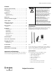
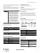
Product labels
All the necessary safety information can be found on the product labels,
which can be found on every controller module (example):
Figure 8: Product label MSR41 Base Module
Explanation of terminology
Table 16
Technical Data
1. In cases where the MSR41 base module
is installed without expander modules
the function output monitoring must
always be realized, the only exceptions
are if the PNP outputs are connected with
another safety relay or a safety PLC.
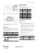
2. Through the use of output monitoring,
it is possible to switch external “power”
contactors within the safety circuit. Such
contactors often deal with large inductive
loads, which during the switching off
phase can create large potential peaks.
For this reason surge suppressors are
highly recommended. Surge suppressors
must be connected parallel to the
external contactors (e.g. Figure 1). They
may never be connected parallel to the
contacts of a MSR45E expander module.
Supply voltage [V] Resistor R [Ω]Condenser C [μF]
24 100 2.2
115 - 230 220 0.2
Part number Base / Expander type
440R-P221AGS MSR41 On/Off
Part number Part number
440R-P4NANS MSR45E Expander Module
440R-ACABL1 Ribbon Cable – Two modules
440R-ACABL2 Ribbon Cable – Three modules
440R-ACABL3 Ribbon Cable – Four modules
440R-ATERM1P Terminal Block Kit – MSR41 (for replacement)
440R-ATERM2C Terminal Block Kit – MSR45E
HW Hardware Version
Safety Level Cat. Safety category according to EN 954-1
Safety Level SIL Safety integrity level according to EN 61508
Safety Level PLe Performance level acc. to EN ISO 13849-1
Power class Power supply
Temperature range Operating temperature range
OSSD Max. current available per OSSD output, at the listed voltage
General data
Nominal working mode Continuous process
Temperature range
Environment temp.: 0 ... +55°C
Stock temp.: -25 ... +70°C
Enclosure rating according EN 60529
Housing
Terminals
IP20
IP20
Conductor connection:
4- pin, terminal strip (plug-in)
Wire cross section:
max 2.5 mm
2
spring clamping technology
Quick mounting Top hat rail 35 mm (EN 50022)