MSR41 Safety Module User Manual
Important User Information Because of the variety of uses for the products described in this publication, those responsible for the application and use of this control equipment must satisfy themselves that all necessary steps have been taken to assure that each application and use meets all performance and safety requirements, including any applicable laws, regulations, codes and standards.
MSR41 Safety Module User Manual Content MSR41 units can only achieve their function as a safety controller module, if the instructions given in this instruction manual and the within mentioned documents are exactly followed, as well as consulting the valid laws and regulations at the time of installation. Should these instructions not be carefully followed, serious injury or death may occur. The installer or system integrator will be fully responsible for a safe integration of this product.
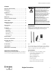
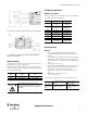
MSR41 Safety Module User Manual Applications Terminal connection diagram Typical applications The following figures shows the connection possibilities for the MSR41 base module: MSR41 controller modules are developed and conceived for typical applications like: • Robotic cells • Assembly lines • Indexing tables • Conveyor systems • Automatic storage facilities Application restrictions MSR41 modules are not intended for application in explosive (EX) or in radioactive environments.
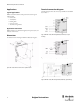
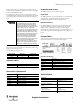
MSR41 Safety Module User Manual LED display elements MSR41 base module Table 2 gives information about the LED on the front side of a MSR41 base module with the basic configuration: Figure 6: MSR41 base module, Micro 400 Light Curtain, automatic start, output monitoring LED Signal / Color / Status Signal / Color / Status OSSD2 +24 V / green / Light curtain not activated (free) 0 V / red / Safe400 Light curtain activated (interrupted) OSSD1 +24 V / green / Light curtain not activated (free) 0 V /
MSR41 Safety Module User Manual Explanation of the terminology Start mode Symbol Meaning t(C) Response time for the MSR41 base module (evaluation time) t(LC) Response time of the light curtain on the label of the light curtain) t(em) Response time for the MSR45E expander module The following start modes are supported by the MSR41: • automatic start or • manual start t(totLCOSSD) Maximum OSSD response time triggered by the light curtain t(totLCEXT) Maximum relay extension module response time
MSR41 Safety Module User Manual function of these contactors, each relay block must have at least one normally closed contact which is fed back in series to the corresponding terminal of the MSR41 base module. Inspection and service Output monitoring: The signal at the corresponding input terminal must be high before the start button is pressed (this means: the normally closed contacts of the external relays must be closed before allowing a start). Inspections 1.
MSR41 Safety Module User Manual General data Safety Related Parameter Net weight 130 g Housing dimensions 111 x 22,5 x 125 mm (incl. plugs) See page 2 Enclosure Type Rating IP20 Operating Temperature [°C (F)] 0 … 55 (32 … 131) Mounting 35mm DIN Rail Housing material Polyamide Conductor Size Max 1 x 2.5 mm2 (14AWG) stranded Vibration according to EN60068-2-6 Amplitude: 0.
MSR41 Safety Module User Manual EC Declaration of Conformity The undersigned, representing the manufacturer Rockwell Automation, Inc. 2 Executive Dr.
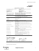
MSR41 Safety Module User Manual Catalogue number 1 440R-P221AGS 440R-P226AGS-NNR 445L-104794-B*** 440R-P4NANS 445L-1**** Series 2 Description MSR41 base module MSR42 base module MSR42 base module customer configuration MSR45E expander module MSR45E expander module customer configuration 1) *Denotes characters representing options that do not impact the standards or directives cited on this DoC 2) If no series number is given, then all series are covered Document Control Number: SEN-0394-B-EN 8 Origin
Technical Support / Technische Unterstützung / Assistance technique / Assistenza tecnica / Asistencia técnica ENGLISH DEUTSCH FRANÇAIS ITALIANO ESPAÑOL PORTUGUÊS POLSKI ČESKY SVENSKA NEDERLANDS Installation of this product must not take place until the installer has obtained a copy of the manufacturer’s instructions in a language which he can understand. This instruction sheet is available in multiple languages at http://rockwellautomation.com/literature.
GuardShield is a trademark of Rockwell Automation, Inc. Guardmaster is a registered trademark of Rockwell Automation, Inc. www.rockwellautomation.com Power, Control and Information Solutions Headquarters Americas: Rockwell Automation, 1201 South Second Street, Milwaukee, WI 53204 USA, Tel: (1) 414.382.2000, Fax: (1) 414.382.