MSR312P Configurable Monitoring Safety Relay with DeviceNet™ Communications USER MANUAL 440R
Important User Information Because of the variety of uses for the products described in this publication, those responsible for the application and use of this control equipment must satisfy themselves that all necessary steps have been taken to assure that each application and use meets all performance and safety requirements, including any applicable laws, regulations, codes and standards.
Configurable Monitoring Safety Relay with DeviceNet™ Communications European Communities (EC) Directive Compliance European Communities (EC) Directive Compliance This product has the CE mark and is approved for installation within the European Union and EEA regions. It has been designed and tested to meet the following directives.
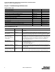
Configurable Monitoring Safety Relay with DeviceNet™ Communications Preface Related Publications Publication Title Publication Number DeviceNet™ Cable System Planning and Installation Manual DN-6.7.2 ControlLogix™ DeviceNet Interface Module User Manual 1756-6.5.19 DeviceNet Media Catalog Guide 1485-CG001A-EN-P Online Information EDS Files: EDS files are available for downloading at http://www.ab.com/networks/eds. Manuals Online: Manuals are available for order or download at http://www.
Configurable Monitoring Safety Relay with DeviceNet™ Communications Table of Contents Table of Contents Important User Information . . . . . . . . . . . . . . . . . . . . . . . . . . . . . . . . . . . . . . . . . . . . . . . . . . . . . . . . . . . . . . . . . . . . . . . . . . . . . . 2 European Communities (EC) Directive Compliance . . . . . . . . . . . . . . . . . . . . . . . . . . . . . . . . . . . . . . . . . . . . . . . . . . . . . . . . . . . 3 EMC Directive . . . . . . . . . . . . . . . . . . . . .
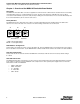
Configurable Monitoring Safety Relay with DeviceNet™ Communications Chapter 1: Overview of the MSR312P DeviceNet Base Module Chapter 1: Overview of the MSR312P DeviceNet Base Module Description The MSR312P offers DeviceNet connection for applications in which network communication is desired. All of the functionality of the DeviceNet interface is contained within the enclosure. The base unit requires two 24V DC power sources.
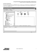
Configurable Monitoring Safety Relay with DeviceNet™ Communications Chapter 1: Overview of the MSR312P DeviceNet Base Module Parameter Configuration For proper operation, the parameters of the MSR312P must be configured. There are 105 parameters in the MSR312P, but only 11 of them are configurable. The parameters can be configured by using RSNetWorx for DeviceNet. Open RSNetWorx and double click on the MSR312P icon.
Configurable Monitoring Safety Relay with DeviceNet™ Communications Chapter 2: Troubleshooting and Maintenance Chapter 2: Troubleshooting and Maintenance Using the Status LED Function Status LED Power up / normal operation Continuous on: green Group 1-2-3 LEDs — Internal fault Continuous on: red — Entering configuration mode 1 flash: red — Input switch fault or reset switch closed during power up 2 flashes: red — Configuration change during operation 3 flashes: red — Current configuration
Configurable Monitoring Safety Relay with DeviceNet™ Communications Chapter 2: Device Parameters Chapter 2: Device Parameters Parameters 1…20—Input Values (read only) Input 1a Value - Input 10b Value The MSR312P supports up to 10 inputs modules to its input side. Each input module has two independent input connections. These are shown as parameters Input 1a Value (the top wiring connection of the module) and Input 1b Value (the bottom connection for input module 1).
Configurable Monitoring Safety Relay with DeviceNet™ Communications Chapter 2: Device Parameters Parameters 30…32—Group Status (read only) Group 1…3 Status These parameters indicates if any of the MSR320P Input Modules assigned to Groups 1, 2, or 3 have an interrupted input. The meaning of the values are: Value 00 01 Meaning Inputs are active—OK At least one input assigned to the Group is interrupted.
Configurable Monitoring Safety Relay with DeviceNet™ Communications Chapter 2: Device Parameters Parameters 40…49—Function Settings (read only) Function Switch Value Module 1…10 These parameters indicate the actual rotary switch settings on MSR320 Input Modules. There is one parameter for each module. Parameter 40 is the input module closest to the base module. These values should be compared to their respective values in nonvolatile memory (Parameters 50…59).
Configurable Monitoring Safety Relay with DeviceNet™ Communications Chapter 2: Device Parameters Parameters 60…69—Group Switch Settings (read only) Group Switch Value Module 1…10 These parameters indicate the actual Group switch setting on the MSR320P Input Modules. There is one parameter for each module. Parameter 60 is the input module closest to the base module. These values should be compared to their respective values in nonvolatile memory (Parameters 70…79).
Configurable Monitoring Safety Relay with DeviceNet™ Communications Chapter 2: Device Parameters Parameter 80—System Faults (read only) This parameter provides indication of a variety of faults that the system may acquire.
Configurable Monitoring Safety Relay with DeviceNet™ Communications Chapter 2: Device Parameters Parameter 87—Output Y34 Idle Action This parameter allows the user to select what value is output when the Semiconductor Output is in the recoverable fault state. The user may choose a preset value, as defined in Semiconductor Output Idle Value, or may opt to specify that the Semiconductor Output holds its last value.
Configurable Monitoring Safety Relay with DeviceNet™ Communications Chapter 2: Device Parameters Parameter 95—Configuration Consistency Value (read only) This parameter indicates the unique value of an installation. The value lies in the range of 0…65535 Parameter 96—Serial Number (read only) This parameter provides a unique identifier when multiples of the same product are being used on a network. The allowable values lie in the range from 0…4294967295.
Configurable Monitoring Safety Relay with DeviceNet™ Communications Chapter 2: Device Parameters 3. Value of Input Module 1: Safety Input 1a-1b Values This consists of 1 byte in (Parameters 1 and 2) 4. Byte Bit 7 Bit 6 Bit 5 Bit 4 Bit 3 Bit 2 In 0 Reserved Reserved Reserved Reserved Reserved Reserved Bit 3 Bit 2 Bit 1 Bit 0 Input 1b Value Input 1a Value Values of Input Modules 1…4: Safety Input 1a-4b Values This consists of 1 byte in (Parameters 1…8) Byte In 0 5.
Configurable Monitoring Safety Relay with DeviceNet™ Communications Chapter 2: Device Parameters 10. State of the Output Groups: Group State This consists of 1 byte in (Parameters 36…38) Byte In 0 Bit 7 Reserved Bit 6 Bit 5 Bit 4 Bit 3 Bit 2 Bit 1 Bit 0 Reserved Group 3 Active Group 3 Ready Group 2 Active Group 2 Ready Group 1 Active Group 1 Ready Bit 3 Bit 2 Bit 1 Bit 0 11.
Configurable Monitoring Safety Relay with DeviceNet™ Communications Chapter 3: Quick Start Guide Chapter 3: Quick Start Guide A simple system is setup to demonstrate messaging. The simple system consists of a 1756-DNB, the MSR312P, and a PanelView 1000. Example 1 Using Change Of State (COS) messaging, the Input Module Values 1…8, the Y34 Output and the System Status will be displayed on the PanelView 1000. This information is located in Option 6 (165) of Parameter Input Assembly (COS). Step 1.
Configurable Monitoring Safety Relay with DeviceNet™ Communications Chapter 3: Quick Start Guide Step 2. Add the MSR312P to the Scan List of DNB scanner. Double-click the 1756-DNB icon. Click on the “Scanlist” tab. Highlight the MSR312P and click the right arrow in the middle of the window to move the MSR312P to the Scanlist. With the MSR312P still highlighted, click on the Edit I/O Parameters button.
Configurable Monitoring Safety Relay with DeviceNet™ Communications Chapter 3: Quick Start Guide Step 3. Set up I/O parameters for the MSR312P. Verify the Strobed and Polled boxes are unchecked. Check the “Change of State/Cyclic” box. Set the Input Size to 2 and the Output Size to 1. We knew the I/O sizes from the parameter help within the MSR312P Parameter (103, 104, 105). Select an appropriate Heartbeat Rate. (Default is ok) Click OK.
Configurable Monitoring Safety Relay with DeviceNet™ Communications Chapter 3: Quick Start Guide Step 4. Configure the MSR312P Inputs. Click on the “Input” Tab. The software automatically maps the Input data at the first available memory locations. Same as selecting “Automap.” Let’s change the location of the data to start at word 10 instead of the default of word 0. Highlight the MSR312P and click Advanced.
Configurable Monitoring Safety Relay with DeviceNet™ Communications Chapter 3: Quick Start Guide Step 5. Map the MSR312P Inputs. In the “Map From:” box, set the Message value to COS. In the “Map To:” box, set the DWord value to 10. This value will be used in the ladder logic program to place the values into the proper memory location. If AutoMap was selected on the previous screen, then the user must adjust the ladder logic program to the appropriate memory location.
Configurable Monitoring Safety Relay with DeviceNet™ Communications Chapter 3: Quick Start Guide Step 6. Configure the MSR312P Outputs. Click on the “Output” Tab. The software automatically maps the Output data at the first available memory locations. Same as selecting “Automap.” Let’s change the location of the data to start at word 10 instead of the default of word 0. Highlight the MSR312P and click Advanced.
Configurable Monitoring Safety Relay with DeviceNet™ Communications Chapter 3: Quick Start Guide Step 7. Map the MSR312P Outputs In the “Map From:” box, set the Message value to COS. In the “Map To:” box, set the DWord value to 10. This value will be used in the ladder logic program to place the values into the proper memory location. If AutoMap was selected on the previous screen, then the user must adjust the ladder logic program to the appropriate memory location.
Configurable Monitoring Safety Relay with DeviceNet™ Communications Chapter 3: Quick Start Guide Step 8. Configure Auto Device Replacement (ADR). To view/edit the auto device replacement parameters, click the ADR tab. Select the “Enable Auto-Address Recovery” box. Click Load Device Config. Select “Configuration Recovery” and “Auto Address Recovery.” ADR is helpful when a unit fails due to mechanical or internal damage and it needs to be replaced.
Configurable Monitoring Safety Relay with DeviceNet™ Communications Chapter 3: Quick Start Guide Step 10. Set up the Ladder Logic Program. A simple ladder logic program transfers the information back and forth between the MSR312P and the PanelView 1000. The address of the Source and Destination must match the addresses set in the 1756-DNB input and output mapping in the previous steps.
Configurable Monitoring Safety Relay with DeviceNet™ Communications Chapter 3: Quick Start Guide Example 2 — Explicit Messaging (UCMM) This example requires a PanelView providing Explicit Messaging and MSR312P Series B. In this case, we are using a PanelView 600 Touch. To configure communication and Indication Panel Builder 32 needs to be installed. Please note that the PanelView must not have the same address like the MSR312P Step 1. Setup PanelView - PC connection.
Configurable Monitoring Safety Relay with DeviceNet™ Communications Chapter 3: Quick Start Guide Step 2. Create PanelView project. Open Panel Builder to configure the PanelView 600 Touch (PV600) for DeviceNet. Click "New Project" and select "Creat a new application" to open the configuration dialog box. Name the project and choose the appropriate PanelView in the "Type" list. Highlight DeviceNet to enable the PV600 Touch for DeviceNet communications and confirm your configuration by clicking "OK".
Configurable Monitoring Safety Relay with DeviceNet™ Communications Chapter 3: Quick Start Guide Step 3. Using Read Tag to indicate Input1a state. It is intended to display the Input 1 status of the First MSR320 Input module (Input 1a). For this a Multistate Indicator Object is used as a Read Tag Select "Indicators" within the "Objects" menu and then "Multistate" to insert the indicator box into the Panel View screen.
Configurable Monitoring Safety Relay with DeviceNet™ Communications Chapter 3: Quick Start Guide The EDS-File defines Parameter 1 as follows: Enter the "Tag Name", in this case "Input1a" and select "Unsigned Integer"(=1 byte) for the "Data Type" according to the parameter size in byte mentioned in the EDS. Check the "Explicit - Client" (Panel iew = Client) box and enter the MSR312P (server) node address. The "Packet Bytes" are set to "2" per default for Read Tags.
Configurable Monitoring Safety Relay with DeviceNet™ Communications Chapter 3: Quick Start Guide Step 4. Using Write Tag to set Semiconductor Output Y34. The Y34 Parameters (Parameter 83…88) are partly configurable (refer to Parameter description). Its output state can be set by using Parameter 83. Therefore a "Momentary" "Push Buttons" Object is added to the Project. Open the Tag Form as described in Step 3.
Configurable Monitoring Safety Relay with DeviceNet™ Communications Chapter 3: Quick Start Guide Verify if the "Single Bit" box is checked and click "Edit Tag…" to configure the communication in the Tag Form Dialog. Select Messaging Type and node address as described in Step 3 and check the "Write Tag" box. Class, Instance and Attribute are derived from the EDS file Parameter 83 description. Select "Bit" for "Data Type" and enter "1" for "Packet Bytes".
Configurable Monitoring Safety Relay with DeviceNet™ Communications Chapter 4: Getting Online via RSNetWorx™ for DeviceNet™ Chapter 4: Getting Online via RSNetWorx™ for DeviceNet™ After connecting the MSR312P to the DeviceNet network, Open RSNetWorx for DeviceNet. Click “Network” then Select “Online.” Select the communication path. Note: You must configure RSlinx first. RSNetWorx requests you to synchronize your offline configuration with the online devices. Click OK.
Configurable Monitoring Safety Relay with DeviceNet™ Communications Chapter 4: Getting Online via RSNetWorx™ for DeviceNet™ Upon successful completion, the devices on the network appear with their description and node address. The MSR312P, in this case, has address 08. Right click on the MSR312P, and select Properties. The General properties of the MSR312P are shown. This window allows the viewing the individual parameters, the I/O data, and the EDS file.
Configurable Monitoring Safety Relay with DeviceNet™ Communications Chapter 4: Getting Online via RSNetWorx™ for DeviceNet™ Click on the parameter tab. The EDS Editor window appears. Click upload to read the current status of the MSR312P. RSNetWorx reads in all the parameters, and then displays them. The window shows the first 14 parameters.
Configurable Monitoring Safety Relay with DeviceNet™ Communications Chapter 4: Getting Online via RSNetWorx™ for DeviceNet™ Click on Monitor to continuously update the values of each parameter. When active, the Monitor field will be a white background and an arrow will scroll down the left side. Click on the I/O tab. The current message type is shown in bold. In this example, Strobed messaging is active.
Configurable Monitoring Safety Relay with DeviceNet™ Communications Chapter 4: Getting Online via RSNetWorx™ for DeviceNet™ Click on the EDS tab. This tab provides the EDS file revision information. Use the View File button to view the contents of the EDS file.
Configurable Monitoring Safety Relay with DeviceNet™ Communications Chapter 4: Getting Online via RSNetWorx™ for DeviceNet™ 38 MSR312-UM001B-EN-P
Configurable Monitoring Safety Relay with DeviceNet™ Communications Chapter 5: Unregister the EDS File Chapter 5: Unregister the EDS File Unregistering the EDS file is only required if the wrong file has been registered. This is not typically required. Close RSlinx if it is already open. Click on tools in RSNetWorx and select EDS Wizard. Click “Next.
Configurable Monitoring Safety Relay with DeviceNet™ Communications Chapter 5: Unregister the EDS File Check “Unregister a device” if replacing an older version of the EDS file. Click “Next.” Click “Next.” Click “Next” to unregister the device. Click “Finish”.
Configurable Monitoring Safety Relay with DeviceNet™ Communications Chapter 6: Register the MSR312P EDS Device Chapter 6: Register the MSR312P EDS Device Open the EDS Wizard. Click “Next.
Configurable Monitoring Safety Relay with DeviceNet™ Communications Chapter 6: Register the MSR312P EDS Device Click “Next.” Click on the device showing in the Product Type window, then click Change icon. Scan through the ICON and select the MSR312P standing next to the safety relay.
Configurable Monitoring Safety Relay with DeviceNet™ Communications Chapter 6: Register the MSR312P EDS Device Click “Next.” Click “Next” to register the device. Click “Finish.
Configurable Monitoring Safety Relay with DeviceNet™ Communications Chapter 7: Off-Line Node Recovery Chapter 7: Off-Line Node Recovery Overview The MSR312P base module is equipped with a function known as Off-Line Node Recovery. Off-Line Node Recovery is used mainly to commission a device on a network. When a new product is put on the network, it is at a default address of Node 63.
Configurable Monitoring Safety Relay with DeviceNet™ Communications Chapter 7: Off-Line Node Recovery If there are multiple faulted devices, they will show up in the list. Devices are identified by the DeviceNet serial number that is unique to every product. The serial number for the MSR312P base module can be located on the name plate or inside the product. Click the “Next” button. If there are multiple faulted units, you can verify which unit you are recovering by flashing the Mod/Net Status LED.
Configurable Monitoring Safety Relay with DeviceNet™ Communications Chapter 7: Off-Line Node Recovery Change the address to the new address (for example, 22) and click “Recover.” Recovery is now complete. For more information on Off-Line Node Recovery refer to the RSNetWorx for DeviceNet User Manual (Publication 1787-6.5.3).
Configurable Monitoring Safety Relay with DeviceNet™ Communications Chapter 7: Off-Line Node Recovery MSR312-UM001B-EN-P 47
Configurable Monitoring Safety Relay with DeviceNet™ Communications Chapter 8: DeviceNet Classes and Objects Chapter 8: DeviceNet Classes and Objects Objects with common attributes are members of the same “Class.” A particular occurrence of an object is called an instance of that class. The class and instance identifier within a DeviceNet connection message will identify exactly what object is being referenced.
Configurable Monitoring Safety Relay with DeviceNet™ Communications Chapter 8: DeviceNet Classes and Objects Class Code 0x0001: Identity Object None of the optional class attributes of the Identity Object will be supported. A single instance (instance 1) of the Identity Object will be supported. The following instance attributes will be supported.
Configurable Monitoring Safety Relay with DeviceNet™ Communications Chapter 8: DeviceNet Classes and Objects A single instance (instance 1) of the DeviceNet Object will be supported. The following instance attributes will be supported.
Configurable Monitoring Safety Relay with DeviceNet™ Communications Chapter 8: DeviceNet Classes and Objects Instance 161 (Diagnostics) Byte 0 1 Bit 7 Bit 6 Current config Any hardware unlike stored failure config Reserved Reserved Bit 5 Bit 4 Bit 3 Bit 2 Bit 1 Bit 0 Config changed during operation Terminal connector is missing Internal Fault (cpFaults1 <> 0) Cross Loop Actual # Modules not equal to NV Invalid code switch setting Reserved Reserved Reserve Lamp 2 Faulty Muting Lamp Reser
Configurable Monitoring Safety Relay with DeviceNet™ Communications Chapter 8: DeviceNet Classes and Objects Instance 171 (20 Point Input w/Single Status Bit) Byte Bit 7 Bit 6 Bit 5 Bit 4 Bit 3 Bit 2 Bit 1 Bit 0 0 Input 4b State Input 4a State Input 3b State Input 3a State Input 2b State Input 2a State Input 1b State Input 1a State 1 Input 8b State Input 8a State Input 7b State Input 7a State Input 6b State Input 6a State Input 5b State Input 5a State 2 Device Fault Reserved Reserved Reserv
Configurable Monitoring Safety Relay with DeviceNet™ Communications Chapter 8: DeviceNet Classes and Objects Instance 2 is the Predefined Group 2 Connection Set Polled I/O Message Connection.
Configurable Monitoring Safety Relay with DeviceNet™ Communications Chapter 8: DeviceNet Classes and Objects The following common services will be implemented for the Connection Object. Implemented for: Service Code Class Instance Service Name 0x0E No Yes Get_Attribute_Single 0x10 No Yes Set_Attribute_Single Class Code 0x0008: Discrete Input Point Object The following class attributes will be supported for the Discrete Input Point Object.
Configurable Monitoring Safety Relay with DeviceNet™ Communications Chapter 8: DeviceNet Classes and Objects Class Code 0x001D: Discrete Input Group Object This object maintains any attributes that apply to all instances of Discrete Input Points so they can be addressed as a group.
Publication MSR312-UM001B-EN-P — October 2008 Supersedes Publication MSR312-UM001A-EN-P — February 2007