
Safety System Display User Manual

MSR245 Manual 6
MSR245-manual-doc page 6 of 6
MSR245 automatically reverts to its default display mode, and indicates ”Receiving no
data”.
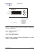
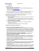
• The text to be displayed by the MSR245 can be checked before the Module is put into
actual operation. To do this, click on the “Download” button or the “Download/Start”
menu option. This causes the PC to send data to the MSR245, simulating an MSR200
Emergency Stop System. After a short delay, this data appears on the MSR245
display.
• The buttons on the right of the “Check” tabbed pane can be used to simulate
operating conditions: Auto Start / Manual Start, EDM active / EDM deactivated, etc.
On the left side, click no interrupt. On the right side, click the different alarm / fault
conditions. Some alarms show (Å) after its name. The display reset switch must be
pressed after de-selecting the alarm.
• The test mode can be terminated by clicking on the “Download / Cancel” menu option.
Specifications
Supply voltage: 24 V
DC
Power consumption: Approximately 500 mW
Operating temperature: - 5
O
C to + 55
O
C
Storage temperature: -25
O
C to + 70
O
C
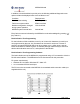
Protection class (per DIN VDE 0470-1): Terminals: IP20. Housing: IP40
Terminals Terminal box with wire protection
Wire cross section 2.5 mm
2
Serial data interface: RS-232, 4800 baud
Drg No: 57600/ Issue No: 1 Feb. 05