
Safety Relay User Manual
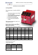


MSR241 DeviceNet for Safety System MSR200
4
______________________________________________________________
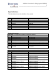
Byte Definitions
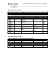
The table below shows the definition of the module
Consumed output byte
Bit High Low
00 K1 energized K1 de-energized
01 K2 energized K2 de-energized
02 Reserved Reserved
03 Reserved Reserved
04 Reserved Reserved
05 Reserved Reserved
06 Reserved Reserved
07 Reserved Reserved
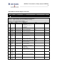
Produced Input bytes
Input byte 1: Configuration and status of MSR210 / MSR211
Bit High Low
00 Device ready Monitoring active
01 Interrupt of any input All inputs valid
02 Cross loop detected No cross loop
03 Automatic reset Supervised reset
04 Relay-output active (Safety system) Relay-output not active (Safety system)
05 EDM dynamic EDM static
06 EDM-loop open EDM-loop closed
07 Internal fault or no basic module
connected
No internal fault and basic module
connected
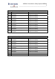
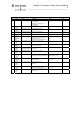
Input-byte2: Status of Inputs of basic module and extension modules 1, 2 and 3
Bit High Low
00 Basic module, input 1 interrupted Basic module, input 1 valid
01 Basic module, input 2 interrupted Basic module, input 2 valid
02 Extension module 1, input 1
interrupted
Extension module 1, input 1 valid (or
module not existent)
03 Extension module 1, input 2
interrupted
Extension module 1, input 2 valid (or
module not existent)
04 Extension module 2, input 1
interrupted
Extension module 2, input 1 valid (or
module not existent)
05 Extension module 2, input 2
interrupted
Extension module 2, input 2 valid (or
module not existent)
06 Extension module 3, input 1
interrupted
Extension module 3, input 1 valid (or
module not existent)
07 Extension module 3, input 2
interrupted
Extension module 3, input 2 valid (or
module not existent)