
Safety Relay Instruction Manual
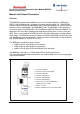

Communication Module MSR240 3
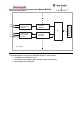
RS232 Interface Description
Data blocks are transmitted continuously through the RS232 interface, at intervals of
approximately 1 sec. The MSR240 is intended to transmit data to an MSR245 Display
Module, or to a PC. The Baud rate is fixed at 4800
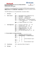
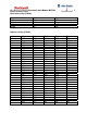
The RS232 protocol uses a 16-byte data block, structured as follows:
1 Start byte: 02
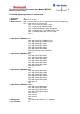
2 Device status: Bit 0: = 1: Unit ready for start. / = 0: Not ready / busy
Bit 1: = 1: Stop signal. / = 0: Inputs OK
Bit 2: = 1: Cross-fault. / = 0: No cross-fault
Bit 3: = 1: Auto start. / = 0: Manual start
Bit 4: = 1: Relay energised. / = 0: Relay de-energised
Bit 5: = 1: Feedback loop dynamic. / = 0: Feedback loop
static
Bit 6: = 1: Feedback loop open if unit is "Ready"
Bit 7: = 1
3 Fault diagnostics: Bit 0: = 1: System bus (SPI) failure. / = 0: ….OK
Bit 1: = 1: Oscillator failure. / = 0: ….OK
Bit 2: = 1: Relay transistor failure. / = 0: ….OK
Bit 3: = 1: Relay contact failure. / = 0: ….OK
Bit 4: = 1: Feedback circuit fault. / = 0: ….OK
Bit 5: = 1: Y40 circuit failure. / = 0: ….OK
Bit 6: = 1: Bus termination plug missing. / = 0: ….OK
Bit 7: = 1
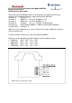
4 - 14 Input modules: activation and wiring:
Bit 0: = 1: Emergency stop (or failure): Input 1
Bit 1: = 1: Emergency stop (or failure): Input 2
Bit 2: = 1: MSR220 Module. / = 0: MSR221 Module
Bit 3: = 1 0 1
Bit 4: = 0 1 1
1- 2- 3-channel detection: Input 2
Bit 5: = 1 0 1
Bit 6: = 0 1 1
1- 2- 3-channel detection: Input 1
Bit 7: = 1
15 Control byte: XOR – conjunction of Bytes 2 through 14
16 End byte: 03