
User guide

16
Troubleshooting
When a failure is detected the relays K1, K2 are de-energized.
The di erent failures are indicated by di erent ashing codes on the LEDs
run 1 and run 2. The failures are split into 2 groups.
Failure group 1:
System failure
On occurrence of such a failure the unit locks out and shows the failure
code, the module can only be reset by switching the unit o and on again.
These failures are only indicated on LEDs run 1 and/or run 2. At the same
time 2 di erent codes can be indicated on the 2 LEDs. The outputs (48 and
58) are always o in this state.
Failure group 2:
Function failure
These failure codes are only displayed on LED run 1 and output 48 while
LED run 2 remains on permanently.
The relays K1, K2 are de-energized in this state, the module is still active and
the relays can be activated by pressing the start button after the failure has
been removed.
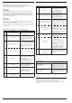
System failure: (indicated only on LEDs run 1 and/or run 2)
No.*
)
Description Measures and notes
0 Internal failure (LEDs o )
If both LEDs are o the relay is
defective and has to be sent
back for examination.
5 Faulty setting
1) The switches on both
channels are not identically
2) The selected setting is not
allowed.
6 Undervoltage detection
Left LED is ashing when the
voltage drops under the allowed
level (< approx. 0.85 UN). After
returned to normal a reset is
made (similar to power up of the
unit).
6 Overvoltage detection
The right LED is ashing when the
voltage rises over the allowedlevel
of > approx. 1,15 UN + 5 % residual
ripple.
7 Input failure
1) A short circuit occurred on
the start button or machine
contact input 2)
2) Both signals of one LC are
not identically (short circuit,
broken wire of defective LC)
8
Failure on output contacts
K1, K2
Please check the output K1, K2
circuit and contact current,
relay has to be repaired.
9
10
11
Internal failure
Please try to evaluate the
circumstances that led to this
fault and check with the
supplier or manufacturer.
12
13
Internal failure The relay has to be repaired.
*) No.: number of ash pulses in a series
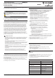
Troubleshooting
Function failure: indication on LED run 1 and output 48
No.*
)
Description Measures and notes
1 LC failure
1) One LC has been interrupted.
2) All LC inputs that are not
used must be bridged:
LC 2: S21-S22, S23-S24
LC 3: S31-S32, S33-S34
2 Failure on start button
1) During start up of the unit
and initialising the start
button must not be pressed
2) The start button must not
be pressed longer than 3 s.
3
Protective operation failure
in feed back circuit
1) An operating mode with feed
back circuit ist selected and and
the circuit connected to S41-S42
is not closed before activation
of K1, K2.
3
Stepping operation
contact failure
1) The machine contact is not
closed in initial position (waiting
for start)
2) With contact type 1 the machine
contact was not closed at the end
of the required rst interruption
of the light curtain.
4
Muting failure
(blocked LC)
1) The selected max. muting
time had been exceeded
(muting lamp on).
4
Muting failure
(lamp)
2) The muting lamp is not
connected between terminals
48 and M1 and M2.
3) The necessary bridge is not
connected between terminal
S41-S42.
4) The muting lamp is defective.
5) The measuring circuit for the
muting lamp is defective,
the unit has to be repaired.
5
Stepping operation
(key failure)
1) Both contacts of the key switch
to select the number of steps
are open
*) No.: number of ash pulses in a series
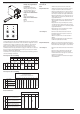
Status indication
run 1 and output 48 are ashing fast with 3 Hz
Muting operation:
Override possible
Minimum one muting sensor is
active, LC 1 is interrupted and the
start button is pressed. After 3 s
with activated start button the
override is started for max. 12 s.
Stepping operation:
Wait for access
The unit is waiting for the required
number of interruptions of the LC
so that the safety relays can be
activated.
Maintenance and repairs
- The device contains no parts that require maintenance.
- In case of failure, do not open the device but send it to manufacturer
for repair.