
User guide

15
Technical Data
Input
Nominal voltage U
N
: DC 24 V
Voltage range:
at max. 5 % residual ripple: 0,85 ... 1,15 U
N
Nominal consumption: max. 170 mA
(no load on semiconductor outputs)
Control voltage on
S21, S23, S31, S33, S41,
S43, S48, S58: DC 23 V at U
N
Control current on
S12, S14, S22, S24,
S32, S34, S42, S44: each 4,5 mA at U
N
Min. voltage on terminals
S12, S14, S22, S24, S32,
S34 S42, S44: DC 16 V
Short circuit protection: internal with PTC
Min. current on M1, M2: 25 mA with active lamp
Output
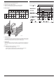
Contacts
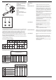
MSR22LM.03: 3 NO contacts
MSR22LM.22: 2 NO, 1 NC contacts
The NC contact must only be used as
monitoring contact !
Contact type: Relay, positive guided
Operate delay typ. at U
N
:
Manual start: max. 50 ms
Automatic start: max. 1,5 s
Automatic restart: max. 55 ms
Release delay (reaction time): max. 30 ms
(max. 50 ms when failure on LC and
only one input channel de-energises)
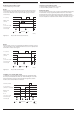
Output voltage: AC 250 V
DC: see Limit curve for arc-free
operation*
)
*
)
see datasheet MSR22LM on www.rockwellautomation.com
Switching of low loads: 100 mV
Thermal current I
th
: 5 A
Switching capacity
to AC 15:
NO contact: 3 A / AC 230 V IEC/EN 60 947-5-1
NC contact 2 A / AC 230 V IEC/EN 60 947-5-1
to DC 13 at 0,1 Hz: 8 A / DC 24 V IEC/EN 60 947-5-1
Electrical life
to AC 15 at 2 A, AC 230 V: 10
5
switching cycles IEC/EN 60 947-5-1
Permissible switching
frequency: max. 1 200 switching cycles / h
Short circuit strength
max. fuse rating: 6 A gL IEC/EN 60 947-5-1
line circuit breaker: C 8 A
Semiconductor outputs
Output (terminal 48 and 58): Transistors, plus-switching
Output voltage: DC 24 V,
max. 100 mA continuous current,
max. 400 mA for 0,5 s internal short
circuit, overtemperature and overload
protection
General Data
Operating mode: Continuous operation
Temperature range
operation: 0 ... + 50 C
storage : - 25 ... + 85 C
altitude: < 2.000 m
Clearance and creepage
distances
rated impuls voltage /
pollution degree: 4 kV / 2 (basis insulation) IEC 60664-1
EMC
Electrostatic discharge: 8 kV (contact) IEC/EN 61 000-4-2
(according to test degree 3)
HF irradiation: 10 V / m IEC/EN 61 000-4-3
Fast transients:
on wires for power supply A1-A2: 2 kV IEC/EN 61 000-4-4
on wires for signals and control: 2 kV IEC/EN 61 000-4-4
Technical Data
Surge voltages
between
wires for power supply: 1 kV IEC/EN 61 000-4-5
between wire and ground: 2 kV IEC/EN 61 000-4-5
HF wire guided: 10 V IEC/EN 61 000-4-6
Interference suppression: Limit value class B EN 55 011
Degree of protection: according to IEC/EN 61 496-1 (1997)
the unit has to be installed in a housing
with protection degree 54.
Housing: IP 40 IEC/EN 60 529
Terminals: IP 20 IEC/EN 60 529
Housing: Thermoplastic with V0 behaviour
according to UL subject 94
Vibration resistance: according to IEC/EN 61 496-1 (1997)
Amplitude 0,35 mm IEC/EN 60 068-2-6
frequency 10 ... 55 Hz
Shock resistance:
Acceleration: 10 g
Impulse length: 16 ms
Number of shocks: 1000 per axis on 3 axis
Climate resistance: 0 / 050 / 04 IEC/EN 60 068-1
Terminal designation: EN 50 005
Wire xing: Terminal screws M 3,5
Box terminal with wire protection
Mounting: DIN rail IEC/EN 60 715
Weight: 320 g
UL-Daten
The safety functions were not evaluated by UL. Listing is a
ccomplished according to requirements of Standard UL 508, “general
use applications”.
Nominal voltage U
N
: DC 24 V
Ambient temperature: 0 … +50°C
Switching capacity:
Ambient temperature 50°C: Pilot duty B300
5A 250Vac G.P.
5A 24Vdc
Semiconductor outputs: 24Vdc, 100 mA
Wire connection: 60°C / 75°C copper conductors only
AWG 20 - 12 Sol Torque 0.8 Nm
AWG 20 - 14 Str Torque 0.8 Nm
nfo
Technical data that is not stated in the UL-Data, can be found
in the technical data section.