
User Manual Owner's manual

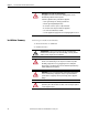
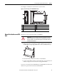
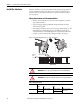

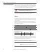
Table Of Contents
- Important User Information
- Preface
- Table of Contents
- About the Interface
- Overview
- Important Interface Considerations
- About the Interface
- Interface Features
- What the Interface Does
- Hardware/Software Compatibility
- Use of the Common Industrial Protocol (CIP)
- Understand the Producer/ Consumer Model
- Specify the Requested Packet Interval (RPI)
- Support of Data Connections
- Chapter Summary
- Install a Guardmaster EtherNet/IP Network Interface
- Configure the Interface for Your EtherNet/ IP Network
- Automation Controller Communications
- Troubleshoot the Interface
- EtherNet/IP Network Interface Specifications
- Interface Web Dialogs
- Configure the RSLinx Ethernet Communication Driver
- Tag Definitions
16 Rockwell Automation Publication 440R-UM009B-EN-P - February 2014
Chapter 2 Install a Guardmaster EtherNet/IP Network Interface
Install the Interface
Install the interface to the left of Guardmaster Safety Relays equipped with an
optical communication bus. There must be no more than 5 mm horizontal
separation between two adjacent relays for the optical communication bus to
operate properly.
Wiring Requirements and Recommendations
• Allow for at least 50 mm (2 in.) between I/O wiring ducts or terminal
strips and the interface.
• Separate wiring by signal type. Bundle wiring with similar electrical
characteristics together.
• Label wiring to all devices in the system. Use tape, shrink-tubing, or other
dependable means for labeling purposes. In addition to labeling, use
colored insulation to identify wiring based on signal characteristics. For
example, you may use blue for DC wiring and red for AC wiring.
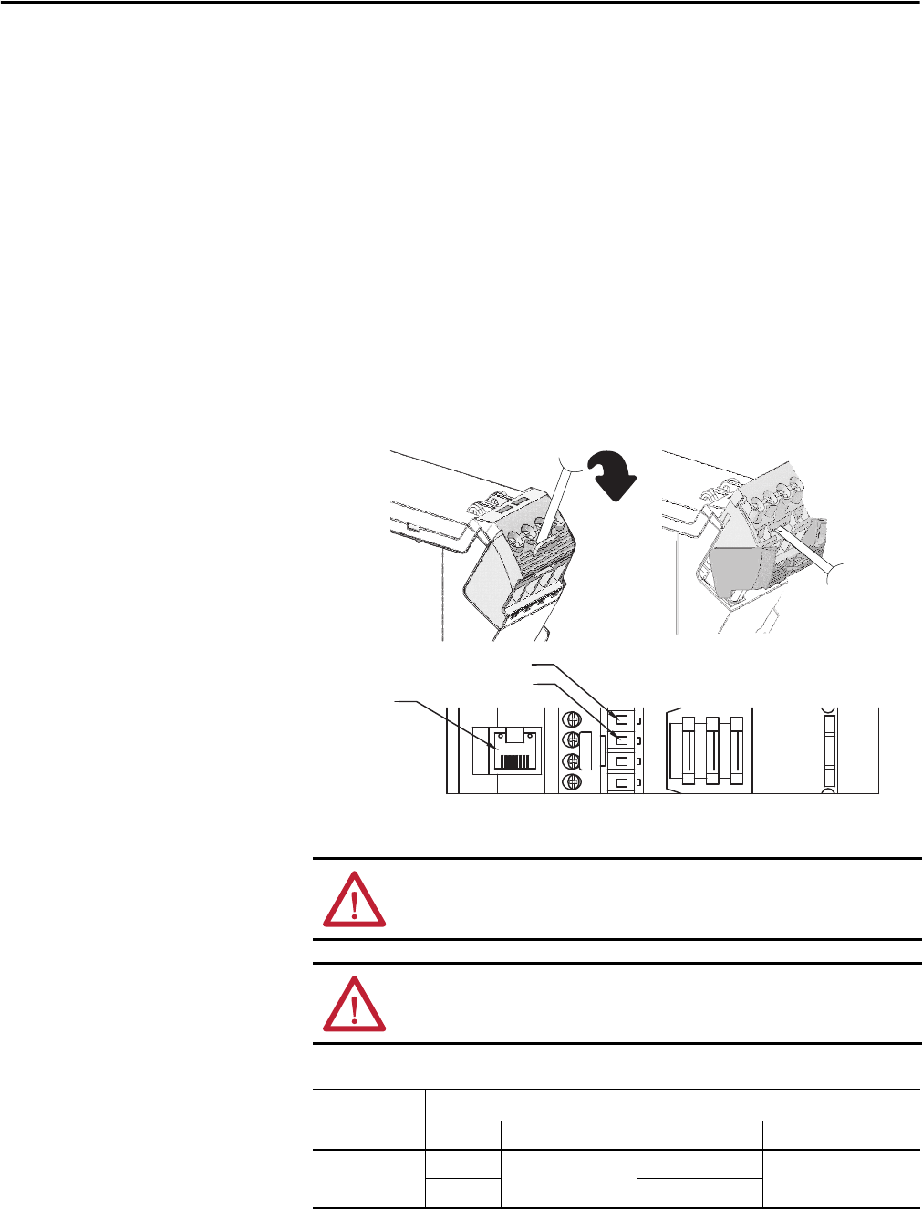
Refer to the following illustration to wire the interface.
ATTENTION: Do not connect 120/240V AC power to the A1/A2 DC supply.
ATTENTION: Do not wire more than two conductors on any single terminal.
Table 1 - Wire Requirements
Wire Size
Type Min Max
440R- ENETR
Solid 0.14 mm
2
(26 AWG) 2.5 mm
2
(14 AWG) Rated @ 90 ºC (194 ºF)
insulation max
Stranded 1.5 mm
2
(16 AWG)
A1 = Supply
A2 = Common
Ethernet
RJ-45
connector
TOP VIEW