User Manual Guardmaster® EtherNet/IP Network Interface Catalog Numbers 440R-ENETR
Important User Information Read this document and the documents listed in the additional resources section about installation, configuration, and operation of this equipment before you install, configure, operate, or maintain this product. Users are required to familiarize themselves with installation and wiring instructions in addition to requirements of all applicable codes, laws, and standards.
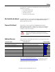
Preface Read this preface to familiarize yourself with the rest of the manual. It provides information concerning: • who should use this manual • the purpose of this manual • related documentation • conventions used in this manual Who Should Use this Manual Use this manual if you are responsible for designing, installing, programming, or troubleshooting control systems that use the 440R-ENETR Guardmaster® EtherNet/IP network interface.
Preface Common Techniques Used in this Manual 4 The following conventions are used throughout this manual: • Bulleted lists such as this one provide information, not procedural steps. • Numbered lists provide sequential steps or hierarchical information. • Italic type is used for emphasis. Rockwell Software products contain extensive tutorials and help screens. We recommend that you use these tutorials and help screens to learn about the products.
Table of Contents Preface Important User Information . . . . . . . . . . . . . . . . . . . . . . . . . . . . . . . . . . . . . . . . 2 Who Should Use this Manual . . . . . . . . . . . . . . . . . . . . . . . . . . . . . . . . . . . . . . . 3 Purpose of this Manual . . . . . . . . . . . . . . . . . . . . . . . . . . . . . . . . . . . . . . . . . . . . . 3 Additional Resources . . . . . . . . . . . . . . . . . . . . . . . . . . . . . . . . . . . . . . . . . . . . . . .
Table of Contents Chapter 4 Automation Controller Communications Overview . . . . . . . . . . . . . . . . . . . . . . . . . . . . . . . . . . . . . . . . . . . . . . . . . . . . . . . . Ethernet Messaging. . . . . . . . . . . . . . . . . . . . . . . . . . . . . . . . . . . . . . . . . . . . . . . I/O Messaging . . . . . . . . . . . . . . . . . . . . . . . . . . . . . . . . . . . . . . . . . . . . . . . . . . . Logix Configuration . . . . . . . . . . . . . . . . . . . . . . . . . . . . . . . . . . . . . .
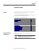
Chapter 1 About the Interface Overview This chapter provides an overview of the Guardmaster EtherNet/IP Network Interface, its primary features, and how to use it. You need to understand the concepts discussed in this chapter to configure your interface and use it in an EtherNet/IP control system. This table lists where to find specific information.
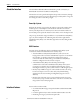
Chapter 1 About the Interface About the Interface The Guardmaster EtherNet/IP Network Interface provide connectivity to EtherNet/IP networks for Guardmaster Safety Relays. The interface is for the optical bus backplane that provides connectivity through two RJ-45 connectors for 2-port pass-through support of daisy chain or ring, and the existing star and tree network topologies.
About the Interface Chapter 1 • Half/full duplex 10 Mbit or 100 Mbit operation • DIN Rail mounting for 440R-ENETR interface • Communication from Guardmaster Safety Relays on the same DIN Rail (mounted immediately to the right of the interface) as the 440R-ENETR interface (when each safety relay is mounted to the right of the interface and each unit is within 5 mm of the next) to controllers on the EtherNet/ IP network • Communication supported by RSLinx® software • IP address assigned via standard BootP o
Chapter 1 About the Interface Use of the Common Industrial Protocol (CIP) Product Firmware Revision/ Software Release GSR DI (Catalog number 440R-D22R2) 2 or later GSR DIS (Catalog number 440R-D22S2) 2 or later GSR EM (Catalog number 440R-EM4R3) 2 or later GSR EMD (Catalog number 440R-EM4R2D) 2 or later GSR GLP (Catalog number 440R-GL2S1P) 2 or later GSR GLT (Catalog number 440R-GL2S2T) 2 or later The adapter uses the Common Industrial Protocol (CIP).
About the Interface Specify the Requested Packet Interval (RPI) Chapter 1 The Requested Packet Interval or RPI is the update rate specified for a particular piece of data on the network. The RPI can be specified for the interface and include all of the Guardmaster Safety Relays in the system. When you add an interface to the I/O configuration of a controller, you must enter the RPI as a parameter. This value specifies how often to produce the data for that device.
Chapter 1 About the Interface Notes: 12 Rockwell Automation Publication 440R-UM009B-EN-P - February 2014
Chapter 2 Install a Guardmaster EtherNet/IP Network Interface Overview This chapter describes how to physically install a Guardmaster EtherNet/IP network interface; and how to mount the interface to DIN Rail. This table lists where to find specific information.
Chapter 2 Install a Guardmaster EtherNet/IP Network Interface ATTENTION: Prevent Electrostatic Discharge This equipment is sensitive to electrostatic discharge, which can cause internal damage and affect normal operation.
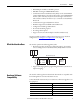
Install a Guardmaster EtherNet/IP Network Interface Chapter 2 Use the figure to identify the external features of your interface. Figure 1 - Physical Features of the 440R-ENETR Interface 1 2 3 4 5 Description Mount the Interface on a DIN Rail Description 1 Removable terminal block 4 Network address rotary switches 2 Status indicators 5 Ethernet network RJ-45 connectors 3 Optical communications link Follow these steps to mount the interface on a DIN Rail.
Chapter 2 Install a Guardmaster EtherNet/IP Network Interface Install the Interface Install the interface to the left of Guardmaster Safety Relays equipped with an optical communication bus. There must be no more than 5 mm horizontal separation between two adjacent relays for the optical communication bus to operate properly. Wiring Requirements and Recommendations • Allow for at least 50 mm (2 in.) between I/O wiring ducts or terminal strips and the interface. • Separate wiring by signal type.
Install a Guardmaster EtherNet/IP Network Interface Chapter 2 Grounding Considerations The grounding and bonding must be of equal potential between all devices in the communication coverage area. ATTENTION: If this equipment is used in a manner not specified by the manufacturer, the protection provided by the equipment may be impaired. Chapter Summary In this chapter, you learned how to install and wire your Guardmaster EtherNet/ IP network interface.
Chapter 2 Install a Guardmaster EtherNet/IP Network Interface Notes: 18 Rockwell Automation Publication 440R-UM009B-EN-P - February 2014
Chapter 3 Configure the Interface for Your EtherNet/ IP Network Overview Before using your interface in an EtherNet/IP network, you need to configure it with an IP address, subnet mask, and optional Gateway address. This chapter describes these configuration requirements and the procedures for providing them. Here are ways you can do this: • Use the Rockwell BootP/DHCP utility, version 2.3 or later, that ships with RSLogix 5000 or RSLinx software.
Chapter 3 Configure the Interface for Your EtherNet/IP Network Configuration Requirements Before you can use your interface, you must configure its IP address, its subnet mask, and, optionally, a gateway address. You can use the Rockwell BootP utility, version 2.3 or later, to perform the configuration. You can also use a DHCP server or the network address switches to configure these parameters.
Configure the Interface for Your EtherNet/IP Network Chapter 3 Gateway Address This section applies to multi-network systems. If you have a single network system, refer to the next section. The Gateway Address is the default address of a network. It provides a single domain name and point of entry to the site. Gateways connect individual physical networks into a system of networks. When a node needs to communicate with a node on another network, a gateway transfers the data between the two networks.
Chapter 3 Configure the Interface for Your EtherNet/IP Network Subnet Mask The subnet mask is used for splitting IP networks into a series of subgroups, or subnets. The mask is a binary pattern that is matched up with the IP address to turn part of the Host ID address field into a field for subnets. EXAMPLE Take Network 2 (a Class B network) in the previous example and add another physical network.
Configure the Interface for Your EtherNet/IP Network Set the Network Address Chapter 3 The interface ships DHCP-enabled and with the switches set to 999. To change the network address, do the following.
Chapter 3 Configure the Interface for Your EtherNet/IP Network Use the Rockwell BootP/ DHCP Utility The Rockwell BootP/DHCP utility is a standalone program that incorporates the functionality of standard BootP software with a user friendly graphical interface. It is located in the Utils directory on the RSLogix5000 software installation CD. The interface must have DHCP enabled (factory default and the network address switches set to an invalid value) to use the utility.
Configure the Interface for Your EtherNet/IP Network Chapter 3 2. Double-click the hardware address of the device you want to configure. The New Entry dialog appears with the device’s Ethernet Address (MAC). 3. Enter the IP Address you want to assign to the device and click OK. The device is added to the Relation List, displaying the Ethernet Address (MAC) and corresponding IP Address, Hostname, and Description (if applicable).
Chapter 3 Configure the Interface for Your EtherNet/IP Network Save the Relation List You can save the Relation List for later use. To save the Relation List, perform the following steps: 1. Select Save As... from the File menu. The Save As dialog appears. 2. Select the folder where you want to save the Relation List. 3. Enter a File name for the Relation List, for example, control system configuration, and click Save. You can leave the Save as type at the default setting: Bootp Config Files (*.bpc).
Configure the Interface for Your EtherNet/IP Network Use DHCP Software to Configure Your Interface Chapter 3 DHCP (Dynamic Host Configuration Protocol) software automatically assigns IP addresses to client stations logging onto a TCP/IP network. DHCP is based on BootP and maintains some backward compatibility. The main difference is that BootP was designed for manual configuration, while DHCP allows for dynamic allocation of network addresses and configurations to newly attached devices.
Chapter 3 Configure the Interface for Your EtherNet/IP Network Notes: 28 Rockwell Automation Publication 440R-UM009B-EN-P - February 2014
Chapter 4 Automation Controller Communications Overview This chapter describes and gives examples of how each type of EtherNet/IP messaging, I/O messaging and Explicit messaging, is used.
Chapter 4 Automation Controller Communications An existing project can be used or a new project can be created to configure EtherNet/IP I/O messaging. To create a new project, perform the following steps. 1. Select File > New from the RSLogix 5000 menu bar. 2. Select the controller type. Then, enter a name for the project and click Next. 3. Select the Security Authority and enter a description. Then, click Finish.
Automation Controller Communications Chapter 4 2. Select the 440R-ENETR, then click Create. 3. Enter a name for the Guardmaster EtherNet/IP network interface. The name will create tags in RSLogix 5000 that can be used to read data from the Guardmaster Safety Relays being scanned by the Guardmaster EtherNet/IP network interface. 4. Enter the IP address of the Guardmaster EtherNet/IP network interface. 5.
Chapter 4 Automation Controller Communications 6. Right-click on an in the Module Definition dialog box and select the Guardmaster Safety Relay that is physically located in that slot position next to the Guardmaster EtherNet/IP network interface. Note: Empty slots between Guardmaster Safety Relays are not supported by the Guardmaster EtherNet/IP network interface at run-time.
Automation Controller Communications Chapter 4 Explicit Messaging Data can be accessed from the Guardmaster EtherNet/IP network interface by non-Logix automation controllers that support EtherNet/IP explicit messaging. This example shows the configuration of an explicit message from a MicroLogix™ 1100 controller to the Guardmaster EtherNet/IP network interface: 1. Set up the MSG instruction to read the data assembly from the Guardmaster EtherNet/IP network interface by configuring the following fields.
Chapter 4 Automation Controller Communications Notes: 34 Rockwell Automation Publication 440R-UM009B-EN-P - February 2014
Chapter 5 Troubleshoot the Interface Overview This chapter describes the different status indicators available in the Guardmaster EtherNet/IP network interface and how to interpret these indicators to help troubleshoot the module.
Chapter 5 Troubleshoot the Interface Table 2 - Status Indicators for 440R-ENETR Interface Module status Network status Link 1 or Link 2 Activity / Status 36 Status Description Off No power applied to device Solid green Device operating normally Flashing green Device needs commissioning due to missing, incomplete, or incorrect configuration. Flashing red/green Module self-test Flashing red Recoverable fault. Complete firmware update, verify address switches.
Appendix A EtherNet/IP Network Interface Specifications Specifications Following are specifications for the Guardmaster EtherNet/IP Network Interface Table 3 - General Specifications – Guardmaster EtherNet/IP Network Interface Specification Description Indicators 2 red/green status indicators: – Module status – Network status (Ports 1 and 2 combined) 2 green/yellow status indicators: – Link 1 status – Link 2 status Power consumption, max 2.2 W @ 26.4V DC Power dissipation, max 0.8 W @ 26.
Appendix A EtherNet/IP Network Interface Specifications Table 4 - Environmental Specifications Specification Description Temperature, operating IEC 60068-2-1 (Test Ad, Operating Cold), IEC 60068-2-2 (Test Bd, Operating Dry Heat), IEC 60068-2-14 (Test Nb, Operating Thermal Shock): -20...+55 °C (-4...
Appendix B Interface Web Dialogs . Work with the Home Page For Information About Page Work with the Home Page 39 Work with the Browse LSR Devices Page 41 Work with the Administrative Settings Pages 42 Use the Network Configuration Page 43 Use the E-mail Configuration Page 44 Use the interface diagnostics home page to access other interface diagnostics web pages and see the following information.
Appendix B Interface Web Dialogs To display and work with the interface diagnostics home page, follow these procedures. IMPORTANT Make sure that your PC Internet LAN setting and your TCP/IP settings are configured to access the subnet on which your interface communicates. 1. From your web browser, enter the interface IP address to see the Home page. Enter the interface IP address to see the home page. 2. From the Home page, complete one of these, as desired. • Click one of the following to access www.
Interface Web Dialogs Work with the Browse LSR Devices Page Appendix B To work with the Browse LSR devices options, follow these procedures. 1. From the Home page, click Browse LSR Devices page. The Browse LSR Devices page opens. 2. In the Refresh Rate field, you can type a refresh rate, noting that the default rate is 15 seconds. 3.
Appendix B Interface Web Dialogs • LSR device #N (where N is 1-6 monitored safety relays) – Device type – Firmware version – Running – Has recoverable fault – Has non-recoverable fault – Operation state 1 – Operation state 2 – Recoverable fault processor 1 – Non-recoverable fault processor 1 – Recoverable fault processor 2 – Non-recoverable fault processor 2 – Communication errors – Communication retries – Non recoverable error count – Recoverable error count Work with the Administrative Settings Pages
Interface Web Dialogs Appendix B Use the Network Configuration Page To use the Network Configuration page to make entries for enabling or disabling DHCP and setting TCP/IP parameters and Ethernet link operation, follow this procedure: 1. From the Web page, click the Network Configuration tab at the top of the page or panel on the left. You see the Network Configuration page. 2. From the Network Configuration tab, complete these entries.
Appendix B Interface Web Dialogs – Ethernet Link Configuration P2 □ Auto □ 10 HDX □ 10 FDX □ 100 HDX □ 100 FDX Use the E-mail Configuration Page To use the E-mail Configuration page to configure the interface to send e-mail messages and text notifications for different communication events, follow this procedure: 1. From the Web page, click the E-mail Configuration tab at the top of the page or panel on the left. You see the E-mail Configuration page. 2.
Appendix C Configure the RSLinx Ethernet Communication Driver Overview To communicate with your adapter over your network, you must configure the RSLinx Ethernet Communication Driver (AB_ETH) or the EtherNet/IP driver (AB-ETHIP). You can configure the AB_ETH driver with the IP addresses of all the Ethernet devices on your system. You need one of these drivers to download the example application programs in this manual. See the table for a list of the contents of this appendix.
Appendix C Configure the RSLinx Ethernet Communication Driver Configure the AB_ETH Driver To configure the AB-ETH Ethernet communication driver perform the following steps: 1. Start the RSLinx software. 2. From the Communications menu, select Configure Drivers. 3. Select Ethernet Devices from the list and click Add/New... 4. Select the default driver name (for example, AB_ETH-1) or type in a name and click OK. The Configure driver dialog opens.
Configure the RSLinx Ethernet Communication Driver Appendix C 5. Click Add New and enter the IP address or Host Name of your Ethernet device (for example, 10.88.70.4, Pump1). 6. Repeat step 6 for each additional Ethernet device you need to access. 7. After entering the IP addresses, click Apply. 8. Click OK to close the Configure driver dialog. The new driver appears in the list of configured drivers. Your list displays the drivers you configured on your workstation. 9. Close the RSLinx software.
Appendix C Configure the RSLinx Ethernet Communication Driver Configure the AB_ETH/IP Driver To configure the AB-ETHIP Ethernet communication driver, perform the following steps. 1. Start the RSLinx software. 2. From the Communications menu, select Configure Drivers. 3. Select EtherNet/IP Devices from the list and click Add/New...
Configure the RSLinx Ethernet Communication Driver Appendix C The Configure Driver dialog box opens. Make sure the Browse Local Subnet button is selected. The RSLinx software browses your local subnet and automatically reads the IP address. 4. Click OK. The AB-ETHIP driver is now configured and appears in the configured drivers window. 5. Close the RSLinx software.
Appendix C Configure the RSLinx Ethernet Communication Driver Notes: 50 Rockwell Automation Publication 440R-UM009B-EN-P - February 2014
Appendix D Tag Definitions Table 6 - GSR DI(S) Module Input Tags Name Data Type Definition Slotx_GSR_DIS_IN01 BOOL IN01 Status - Indicates whether input circuit 1 is On or Off. 0 = The input channel is Off. 1 = The input channel is On. Slotx_GSR_DIS_IN02 BOOL IN02 Status - Indicates whether input circuit 2 is On or Off. 0 = The input channel is Off. 1 = The input channel is On.
Appendix D Tag Definitions Table 6 - GSR DI(S) Module Input Tags Name Data Type Definition Slotx_GSR_DIS_S42 BOOL S42 Status – Indicates whether terminal S42 of circuit IN02 is On or Off. 0 = The terminal is Off. 1 = The terminal is On. Slotx_GSR_DIS_L12 BOOL L12 Status – Indicates whether terminal L12 is On or Off. 0 = The terminal is Off. 1 = The terminal is On. Slotx_GSR_DIS_S34 BOOL S34 Status – Indicates whether terminal S34 is On or Off. 0 = The terminal is Off. 1 = The terminal is On.
Tag Definitions Appendix D Table 7 - GSR DI(S) NonRecoverableFault_A and NonRecoverableFault_B Fault Codes Fault Code Description Corrective Action 06H Safety mat wiring detected on one of the input pairs while the safety relay is configured for ‘OR’ logic Do one of the following: • If there are no safety mats, check the input wiring (safety mat wiring is crossed from normal dual-channel device wiring) • Change the safety relay to ‘AND’ logic.
Appendix D Tag Definitions Table 8 - GSR EM Module Input Tags 54 Name Data Type Definition Slotx_GSR_EM_SingleWireSafetyIn BOOL Single Wire Safety Input Status – Indicates whether the Single Wire Safety input (L12) is On or Off. 0 = The Single Wire Safety input signal is Off. 1 = The Single Wire Safety input signal is On. Slotx_GSR_EM_SafetyOutput BOOL Safety Output Status – Indicates whether the safety output channels are On or Off. 0 = The safety output channels are Off.
Tag Definitions Appendix D Table 9 - GSR EMD Module Input Tags Name Data Type Definition Slotx_GSR_EMD_SingleWireSafetyIn BOOL Single Wire Safety Input Status – Indicates whether the Single Wire Safety input (L12) is On or Off. 0 = The Single Wire Safety input signal is Off. 1 = The Single Wire Safety input signal is On. Slotx_GSR_EMD_B1State BOOL B1 Status – Indicates whether input B1 is On or Off. 0 = The input is Off. 1 = The input is On.
Appendix D Tag Definitions Table 10 - GSR EM(D) NonRecoverableFault_A and NonRecoverableFault_B Fault Codes 56 Fault Code Description Corrective Action 00H No fault None 01H RAM test fault 02H Stack over-/under-flow 03H Configuration mismatch between Processors A and B 04H Internal timing fault 05H EEPROM read/write failure Do one of the following: • Power cycle the safety relay. • Reconfigure the safety relay.
Tag Definitions Appendix D Table 10 - GSR EM(D) NonRecoverableFault_A and NonRecoverableFault_B Fault Codes Fault Code Description 14H-18H Internal plausibility test fault 19H Relay contact fault K1 1AH Relay contact fault K2 Corrective Action Do one of the following: • Power cycle the safety relay. 1CH Relay contact fault K4 • Reconfigure the safety relay. • Validate the electrical installation and appropriate 1DH, 1EH Internal plausibility test fault.
Appendix D Tag Definitions Table 11 - GSR GLP Module Input Tags 58 Name Data Type Definition Slotx_GSR_GLP_S12_S22_Status BOOL S12, S22 Status – Indicates whether two channel input channel S12/S22 is On or Off. 0 = The two channel input is Off. 1 = The two channel input is On. Slotx_GSR_GLP_SingleWireSafetyIn BOOL Single Wire Safety Input Status – Indicates whether the Single Wire Safety input (L12) is On or Off. 0 = The Single Wire Safety input signal is Off.
Tag Definitions Appendix D Table 11 - GSR GLP Module Input Tags Name Data Type Definition Slotx_GSR_GLP_NonRecoverableFault_A SINT Non-Recoverable Fault Processor A – Indicates a nonrecoverable fault has been recorded by Safety Processor A. See Table 12 on page 60 for a list of nonrecoverable fault codes. Slotx_GSR_GLP_NonRecoverableFault_B SINT Non-Recoverable Fault Processor B – Indicates a nonrecoverable fault has been recorded by Safety Processor B.
Appendix D Tag Definitions Table 12 - GSR GLP NonRecoverableFault_A and NonRecoverableFault_B Fault Codes 60 Fault Code Description Corrective Action 00H No fault None 03H Jitter fault 04H Proximity Sensor 1 (P12) stuck at High fault: Potential damage or misalignment of the Proximity Sensor (e.g. exceeding maximum sensing distance, both sensors detecting a space). 04H Proximity Sensor 2 (P22) stuck at High fault. 06H Proximity Sensors cross fault.
Tag Definitions Appendix D Table 12 - GSR GLP NonRecoverableFault_A and NonRecoverableFault_B Fault Codes Fault Code Description Corrective Action 0EH Mismatch between current switch settings and setting stored during power-up. Do one of the following: • Change the switch settings to the correct values. • Power cycle the safety relay. • Reconfigure the safety relay. If the fault persists, contact your local Rockwell Automation technical support representative.
Appendix D Tag Definitions Notes: 62 Rockwell Automation Publication 440R-UM009B-EN-P - February 2014
Rockwell Automation Support Rockwell Automation provides technical information on the Web to assist you in using its products. At http://www.rockwellautomation.com/support you can find technical and application notes, sample code, and links to software service packs. You can also visit our Support Center at https://rockwellautomation.custhelp.com/ for software updates, support chats and forums, technical information, FAQs, and to sign up for product notification updates.