
Installation Instructions Owner manual

8 Guardmaster® EtherNet/IP™ Network Interface
Publication 440R-IN078A-EN-P - January 2014
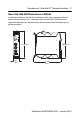
1. Position the interface module on an IEC standard (35 x 7.5 x 1 mm)
top-hat DIN rail at a slight angle (DIN rail: Allen-Bradley part number
199-DR1; 46277-3; EN50022).
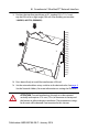
2. Press down firmly to install the interface on a DIN rail.
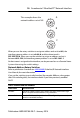
3. Set the network address rotary switches to the desired value. See page 9
,
Set the Network Address, for more information on setting the IP address.
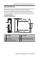
ATTENTION: To avoid overheating, the unit must be mounted
vertically and requires 37.4 mm (1.5 in) of clearance at the top and
the bottom to allow adequate ventilation. The temperature ratings
for the unit will be derated if not mounted in this manner.