
Installation Instructions Owner manual

Guardmaster® EtherNet/IP™ Network Interface 17
Publication 440R-IN078A-EN-P - January 2014
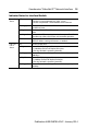
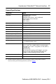
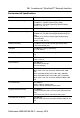
General Specifications
Attribute Value
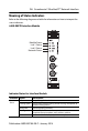
Indicators 2 red/green status indicators:
– Module status
– Network status (Ports 1 and 2 combined)
2 green/yellow status indicators:
– Link 1 status
– Link 2 status
Power consumption, max. 2.2 W @ 26.4V DC
Power dissipation, max. 0.8 W @ 26.4V DC
Thermal dissipation, max. 2.7 BTU/hr @ 26.4V DC
Module input 10...28V DC @ 1000 mA
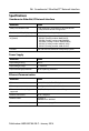
Dimensions (HxWxD), approx. 111.4 x 22.5 x 113.6 mm (4.39 x 0.89 x 4.47 in.)
Enclosure type rating None (open-style)
Terminal base screw torque 0.8 Nm (7 lb-in)
Weight, approx. 180 g (0.4 lb)
Wiring category
(1)
1 – on power ports
1 – on communications ports
Wire size Power connections:
0.34... 2.1 mm
2
(22...14 AWG) solid or stranded copper
wire rated @ 75 °C (167 °F ) or greater, 1.2 mm (3/64 in.)
insulation max.
Ethernet wiring:
RJ45 connector according to IEC 60603-7, 2 or 4 pair
Category 5e min cable according to TIA 568-B.1 or
Category 5 cable according to ISO/IEC 24702.
North American temp code T6
IEC temp code T6
(1)
Use this Conductor Category information for planning conductor routing. Refer to Industrial
Automation Wiring and Grounding Guidelines, publication 1770-4.1.