Installation Instructions Guardmaster® EtherNet/IP™ Network Interface Catalog number 440R-ENETR Table of Contents Topic Page Important User Information 2 Environment and Enclosure 3 Preventing Electrostatic Discharge 4 About the Interface 5 Before You Begin 6 Determine Compatibility 6 Install the Interface 6 Set the Network Address 9 Replace the Interface 11 Wire the Interface 12 Meaning of Status Indicators 14 Specifications 16
Guardmaster® EtherNet/IP™ Network Interface Important User Information Solid-state equipment has operational characteristics differing from those of electromechanical equipment. Safety Guidelines for the Application, Installation and Maintenance of Solid State Controls (publication SGI-IN001_-EN-P available from your local Rockwell Automation sales office or online at http://www.rockwellautomation.
Guardmaster® EtherNet/IP™ Network Interface 3 Environment and Enclosure ATTENTION: This equipment is intended for use in a Pollution Degree 2 industrial environment, in overvoltage Category II applications (as defined in IEC 60664-1), at altitudes up to 2000 m (6562 ft) without derating. This equipment is not intended for use in residential environments and may not provide adequate protection to radio communication services in such environments. This equipment is supplied as open-type equipment.
Guardmaster® EtherNet/IP™ Network Interface Preventing Electrostatic Discharge ATTENTION: This equipment is sensitive to electrostatic discharge, which can cause internal damage and affect normal operation. Follow these guidelines when you handle this equipment: • • • • • • Touch a grounded object to discharge potential static. Wear an approved grounding wrist strap. Do not touch connectors or pins on component boards. Do not touch circuit components inside the equipment.
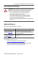
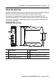
Guardmaster® EtherNet/IP™ Network Interface 5 About the Interface Read this publication for information about the Guardmaster EtherNet/IP network interface, a communications interface for Guardmaster safety relays. This interface is designed for the Guardmaster safety relay optical bus that provides connectivity to an EtherNet/IP network with two RJ-45 connectors for two port pass-through to support daisy-chain or ring, and the existing star and tree network topologies.
Guardmaster® EtherNet/IP™ Network Interface Before You Begin To effectively use the interface, note the following considerations. Determine Compatibility RSLogix 5000™ software version 19, or greater, must be used for the 440R-ENETR Add-on Profile.
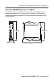
Guardmaster® EtherNet/IP™ Network Interface 7 Mount the 440R-ENETR Interface on a DIN Rail Install the interface to the left of Guardmaster safety relays equipped with an optical communications bus. There must be no more than 5 mm horizontal separation between two adjacent relays for the optical communication bus to operate properly. 105.8 (4.2) 111.4 (4.4) 22.5 (0.9) 113.6 (4.
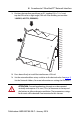
Guardmaster® EtherNet/IP™ Network Interface 1. Position the interface module on an IEC standard (35 x 7.5 x 1 mm) top-hat DIN rail at a slight angle (DIN rail: Allen-Bradley part number 199-DR1; 46277-3; EN50022). 2. Press down firmly to install the interface on a DIN rail. 3. Set the network address rotary switches to the desired value. See page 9, Set the Network Address, for more information on setting the IP address.
Guardmaster® EtherNet/IP™ Network Interface 9 WARNING: If you connect or disconnect the communications cable with power applied to this module or any device on the network, an electrical arc can occur. This could cause an explosion in hazardous location installations. Be sure that power is removed or the area is nonhazardous before proceeding. ATTENTION: Do not remove or replace an interface module while power is applied. Interruption of the device can result in unintentional operation or machine motion.
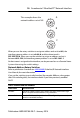
Guardmaster® EtherNet/IP™ Network Interface This example shows the network address set at 163. 8 7 9 01 6 54 8 7 A 2 3 9 01 8 7 6 54 B 2 3 9 01 6 54 C 2 3 When you use the rotary switches to assign an address and set it to 001, the interface gateway address is set to 0.0.0.0, and the subnet mask is 255.255.255.0. When you use the switches to assign an address and set it between 002...254, the interface gateway address is set to 192.168.1.1.
Guardmaster® EtherNet/IP™ Network Interface 11 WARNING: When you change switch settings while power is on, an electrical arc can occur. This could cause an explosion in hazardous location installations. Be sure that power is removed or the area is nonhazardous before proceeding. Replace the Interface Use these procedures to install a replacement interface to an existing system. 1. Disconnect the Ethernet connector(s) from the interface. 2.
Guardmaster® EtherNet/IP™ Network Interface WARNING: If you connect or disconnect the communications cable while power is applied to this module or any device on the network, an electrical arc can occur. This could cause an explosion in hazardous location installations. Be sure that power is removed or the area is nonhazardous before proceeding. 3. Use a small flat blade screwdriver to pull down the DIN rail locking clip and lift the module off the DIN rail. 4.
Guardmaster® EtherNet/IP™ Network Interface 13 Wire the Interface Ethernet RJ-45 connector A1 = Supply A2 = Common TOP VIEW ATTENTION: Do not connect 120/240V AC power to the A1/A2 DC supply. WARNING: Do not wire more than two conductors on any single terminal. WARNING: To comply with the CE Low Voltage Directive (LVD), this equipment must be powered from a Safety Extra Low Voltage (SELV) or Protected Extra Low Voltage (PELV) compliant source.
Guardmaster® EtherNet/IP™ Network Interface Meaning of Status Indicators Refer to the following diagram and table for information on how to interpret the status indicators. 440R-ENETR Interface Module Module Status Link 1 Status Link 2 Status Network Status Indicator Status for Interface Module Indicator Status Description Module Status Off No power applied to device Flashing green Device needs commissioning due to missing, incomplete, or incorrect configuration.
Guardmaster® EtherNet/IP™ Network Interface 15 Indicator Status for Interface Module Network Status Link 1 or Link 2 Status Off Device is not on-line: - Device has not completed dup_MAC_id test. - Device not powered - check module status indicator Flashing green Device is on-line but has no CIP connections in the established state. Solid green Device on-line and has CIP connections in the established state. Flashing red One or more CIP connections in timed-out state.
Guardmaster® EtherNet/IP™ Network Interface Specifications Guardmaster EtherNet/IP Network Interface Attribute Value Safety classification value • Not applicable. This product is not intended for safety-related control or diagnostics. Guardmaster Safety Relay capacity • 6 Guardmaster safety relays Supported modules (FW Rev 2.
Guardmaster® EtherNet/IP™ Network Interface 17 General Specifications Attribute Value Indicators 2 red/green status indicators: – Module status – Network status (Ports 1 and 2 combined) 2 green/yellow status indicators: – Link 1 status – Link 2 status Power consumption, max. 2.2 W @ 26.4V DC Power dissipation, max. 0.8 W @ 26.4V DC Thermal dissipation, max. 2.7 BTU/hr @ 26.4V DC Module input 10...28V DC @ 1000 mA Dimensions (HxWxD), approx. 111.4 x 22.5 x 113.6 mm (4.39 x 0.89 x 4.47 in.
Guardmaster® EtherNet/IP™ Network Interface Environmental Specifications Attribute Value Temperature, operating IEC 60068-2-1 (Test Ad, Operating Cold), IEC 60068-2-2 (Test Bd, Operating Dry Heat), IEC 60068-2-14 (Test Nb, Operating Thermal Shock): -20...55 °C (-4...131 °F) Temperature, surrounding air max.
Guardmaster® EtherNet/IP™ Network Interface 19 Certifications Certification (when product is marked)(1) Value c-UL-us UL Listed Industrial Control Equipment, certified for US and Canada. See UL File E192904. CE European Union 2004/108/EC EMC Directive, compliant with: EN 61326-1; Meas./Control/Lab.
Rockwell Automation Support Rockwell Automation provides technical information on the Web to assist you in using its products. At http://www.rockwellautomation.com/support/, you can find technical manuals, a knowledge base of FAQs, technical and application notes, sample code and links to software service packs, and a MySupport feature that you can customize to make the best use of these tools.