
Safety Limit Switch User Manual

2
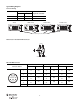
Typical Wiring Diagrams
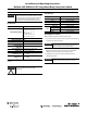
Connector Ratings
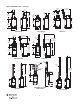
N5 Connector 2-Circuit 5-Pin Mini Connector
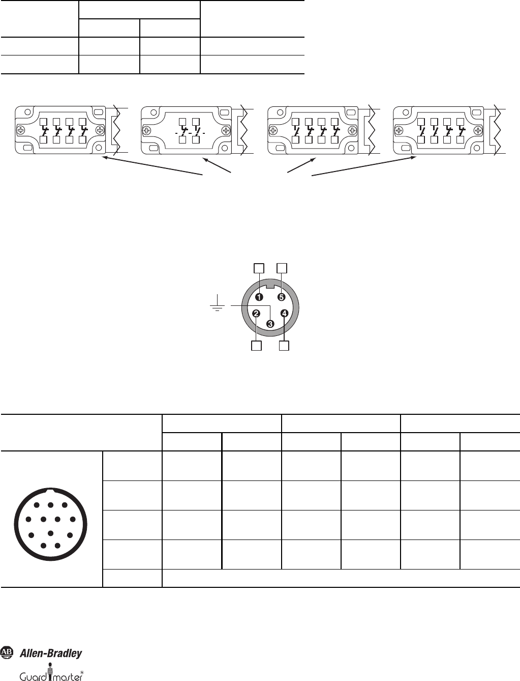
M9 12-Pin M23 Connector
Max. Ratings
Applicable StandardsAC DC
5-Pin Mini (M12) 300V, 2.5 A 300V, 2.5 A IEC 61076-2-101:2003
12-Pin (M23) 60V, 2.5 A 60V, 2.5 A IEC 61076-2-101:2003
4 N.C. 1 N.O. 1 N.C. 1 N.O. 3 N.C. 2 N.O. 2 N.C.
Same polarity this side of block
41 31 21 11
42 32 22
12
11 23
12 24
43 31 21 11
44 32 22 12
43 33 21 11
44 34 22 12
1 (N.C.)
Auxiliary Circuit (N.O.)
23
11
24
12
Connector Pinout
4 N.C. 3 N.C., 1 N.O. 3 N.C.
Terminal Contact Terminal Contact Terminal Contact
1
3
11
12
N.C.
11
12
N.C.
11
12
N.C.
4
6
21
22
N.C.
21
22
N.C.
21
22
N.C.
7
8
31
32
N.C.
31
32
N.C.
33
34
N.O.
9
10
41
42
N.C.
43
44
N.O.
43
44
N.O.
12 Ground
2
3
45
6
1
11
10
9
8
7
12