
Installation Instructions

Rockwell Automation 440N-IN013A-EN-P—October 2014
2 SensaGuard™ 18 mm Plastic Barrel Unique Coding
Protection
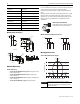
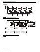
Dimensions [mm (in.)]
Mode of Operation
Status indicators:
• “Power/Fault” LED illuminates green: Door/guard closed,
safety outputs active.
• “Power/Fault” LED illuminates red: Door/guard open,
safety outputs off.
• “Power/Fault” LED flashes red: Unit failure. See Diagnostic
section on page 3.
• “Power/Fault” LED flashes green: Safety inputs off.
Short-circuit Incorporated
Current Limitation Incorporated
Overload Incorporated
False Pulse Incorporated
Transient Noise Incorporated
Reverse Polarity Incorporated
Overvoltage Incorporated
Thermal Shutdown/Restart Incorporated
Electrical Life
10 x 10
6
30 mm Actuator
48.92
[1.926]
19.81
[0.78]
22.22
[0.875]
48.92
[1.926]
19.81
[0.78]
22.22
[0.875]
30.40
[1.197]
16.84
[0.663]
3.17
[0.125]
4.57
[0.18]
2 places
Dia.
Sensor
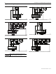
18 mm Actuator
67.06
[2.640]
2.03
[.080]
M18X1
36.47
[1.436]
13.72
[0.54]
15.87
[0.625]
36.47
[1.436]
13.72
[0.54]
15.87
[0.625]
4.57
[0.180]
DIA
19.81
[0.78]
3.17
[0.125]
15.42
[0.607]
2 PLACES
Mounting Information
Use non-removable screws, bolts, or nuts to mount the switch and
actuator. Do not over torque the mounting hardware.
Position the switch and actuator so they are aligned with each
other.
Mount the switch and actuator to removable guard, door, or gate.
Keep the switch and actuator within the sensing range below.
This switch is not meant to be fully embedded in metal. Use the
stainless steel version (440N-Z21S17* or 440N-Z21U17*) for
embedding.
Nut Torque Specification
Plastic Barrel Switch: 2.26 N•m (20 in•lb)
Plastic Actuators: 2.26 N•m (20 in•lb)
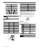
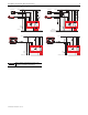
Minimum Distance Between Sensors
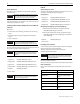
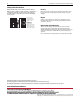
Misalignment Curve
18 mm Unit with 18 mm Target
There must be a minimum spacing of 4 mm
(0.157in.) if actuator and sensor face approaches
laterally. This will prevent false triggering due to
the side lobe areas.
18 mm Actuator
75 mm
Sensor
1
Sensor
2
30 mm Actuator
100 mm
Sensor
1
Sensor
2
Lateral Misalignment Tolerance—mm (in)
Face to Face Distance—mm
-15
(-0.59)
-10
(-0.39)
-5
(-0.19)
0
5
(0.19)
10
(0.39)
15
(0.59)
0
5
10
15
20
25
-25
(-0.98)
-20
(-0.787)
20
(0.787)
25
(0.98)
Side Lobe Side Lobe
Assured Sensing
Distance
OFF OFF
ON
Assured Sensing
Distance
OFF
IMPORTANT