
Installation Instructions Owner's manual

PN-75056-179 ver 04 April 2012
SensaGuard
TM
Installation Instructions 7
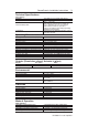
Note: Refer to Technical Specifications for Certification information and ratings.
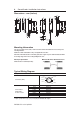
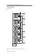
Yel
Red
White
Gray
Pink
Blue
24V DC
Power
Supply
1606
Sensor 1
+24
RT
Sensor 2
Brown
Brown
Gray
Pink
White
Yel
Red
Blue
Sensor 3
Brown
Yel
Red
White
Gray
Pink
Blue
A2
S21
S11 41332313S12S52
42342414
A1S34
S22
440R-N23127
Actuator 1
Actuator 2
Actuator 3
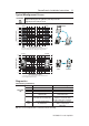
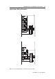
Initial Conditions:
All actuators are in sensing
distance.
Actuator 1 is moved out of
sensing range.
Sensor 2 drops the 24 volts
(red and yellow) from Sensor 1
OSSD outputs.
Green LED flashes.
Sensor 3 drops the 24 volts
(red and yellow) from Sensor 2
OSSD outputs.
Green LED flashes.
0 ms
54 ms 72 ms 90 ms
Actuator 1 is out of sensing
range.
Actuator 2 and 3 are in
sensing range.
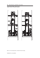
Actuator 1 is moved into sensing
range.
Sensor 1 OSSD outputs are
energized.
Sensor 2 OSSD inputs (red and yellow)
transition to 24V DC from Sensor 1
OSSD outputs.
Sensor 2 OSSD outputs are energized
Sensor 3 OSSD inputs (red and
yellow) transition to 24V DC from
Sensor 2 OSSD outputs.
Sensor 3 OSSD outputs are
energized.
0 ms
360 ms 378 ms 396 ms
OFF
ON
Unit Response Time (does not include safety relay response time)