
Installation Instructions Owner's manual
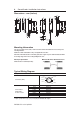
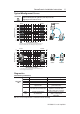
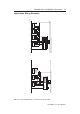
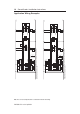

Typical Misalignment Curves
Diagnostics
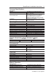
Unit Indicators (per IEC 60073)
State Status Troubleshooting
Off Not Powered NA
Status/Diag Red Not Safe, OSSD not active NA
LED Green Safe, OSSD active NA
Green flash Power up test or OSSD Check 24V DC or OSSD inputs
inputs not valid (yellow and red wire)
Red Flash 1 Hz Flash Recoverable Fault Recoverable fault —check OSSD
4 Hz Flash Non-recoverable Fault outputs are not shorted to GND,
24V DC or each other. Cycle power.
Amber 1 Hz Flash margin indicator Sensor is reaching max. sensing
Flash safe, OSSD active distance; re-align sensor
with actuator
PN-75056-179 ver 04 April 2012
SensaGuard
TM
Installation Instructions 5
Note: Refer to Technical Specifications for Certification information and ratings.
Allow a minimum spacing of 9 mm (0.35 in.) if the actuator and sensor faces
approach laterally (from the y-direction). This will prevent false
triggering due to the side lobe areas.
x
z
y
Sensor
Actuator
Actuator
5
10
15
20
25
30
35
SIDE
LOBES
Sensing Distance* (mm)
0
SIDE
LOBES
ASSURED
SENSING
DISTANCE
*when the actuator approaches the sensor in the x-direction or
from above (z-direction) and is misaligned in the y-direction
Sensor Actuator
5
10
15
20
25
30
35
Sensing Distance** (mm)
0
23
23
50
40
30
20
30
0
10
20
10
40
50
50
40
30
20
30
0
10
20
10
40
50
Misalignment (mm)
** when the actuator approaches the sensor in the x-direction
and is misaligned in the z-direction.
Sensor Actuator
ASSURED
SENSING
DISTANCE
x
Sensor Actuator
z
z
ATTENTION: