
Installation Instructions Owner's manual
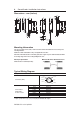
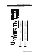
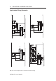
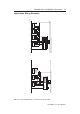
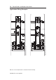

Dimensions - mm (inches)
Mounting Information
Use non-removable screws, bolts, or nuts to mount the switch and actuator. Do not over torque the
mounting hardware.
Position the switch and actuator so they are aligned with each other.
Mount the switch and actuator to removable guard, door or gate. Keep the switch and actuator within
the sensing range shown in the sensing/misalignment curve.
Nut Torque Specification
Switch/Actuator: 2.26 N•M (20 in•lbs)
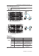
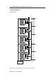
Typical Wiring Diagram
Description Plastic
8-Pin Micro (M12)
Grey Safety A
Red Safety A+
Pink Safety B
8-Pin Cordset Yellow Safety B+
889D-F8AB-* White Aux A
or cable version Brown 24V DC+
Blue Gnd / 0V
Green N/A
* Replace symbol with 2 (2 m), 5 (5 m) or 10 (10 m) for standard cable lengths.
PN-75056-179 ver 04 April 2012
4 SensaGuard
TM
Installation Instructions
200.00mm
24.99
(0.984)
88.14
(3.47)
10.66
(0.42)
7.11
(0.28)
6.78
(0.267)
4.57
(0.18)
¯ 5.08
(¯ 0.2))
4.57
(0.18)
68.31
(2.689)
18.54
(0.73)
72.9
(2.87)
77.98
(3.07)
20.65
(0.813)
24.99
(0.984)
88.14
(3.47)
20.65
(0.813)
4.57
(0.18)
18.54
(0.73)
10.67
(0.42)
13.41
(0.528)
9.96
(0.392)
QD
CONNECTOR
VERSION
M12 x 1
¯ 9.7
(¯ 0.38)
4.57
(0.18)
¯ 5.08
(¯ 0.2)
4.57
(0.18)
77.98
(3.07)
62.53
(2.462)
57.96
(2.282)
82.55
(3.25)
2-24V DC+
1-Aux A
7-0V
6-Safet
y
B
3-N/A
8-Safety A+
4-Safety B+
5-Safety A
Minimum Distance Between Sensors