
Installation Instructions Owner's manual

Technical Specifications
Safety Ratings
Standards IEC 60947-5-3, IEC 61508, ISO 13849-1
Safety Classification PLe Per ISO 13849-1, SIL 3 Per IEC 61508
PFH
D
: 1.12 x 10
-9
Dual channel interlock may be suitable for
Functional Safety Data use in application up to PLe (according to
ISO 13849-1) and for use up to SIL3
systems (according to IEC 62061) depending
application characteristics.
Certifications CE marked for all applicable directives, cULus
(UL 508), and TÜV.
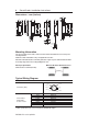
Operating Characteristics
Sensing Distance, Assured Make (mm) 15
Sensing Distance, Assured OFF (mm) 35
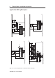
Typical Misalignment See misalignment curve
Repeat Accuracy 10% of sensing range
Maximum output current (all outputs, mA) 200
Input Current 50 mA (no load supply current)
Operational Current, Min. ≥ 1 mA DC
Off-state Current < 0.5 mA DC
Maximum # of switches, connected in series Unlimited. See unit response time section
Operating Voltage 24V DC +10% / -15%
Frequency of operating cycle 1 Hz
Response Time (Off) 54 ms first switch, 18 ms additional for each switch
Case Material Valox
®
DR 48
Actuator Material Valox
®
DR 48
Outputs (Guard door closed, Actuator in place)
Outputs Description Status
Safety 2 x PNP, 0.2 A max. ON (+24vdc)
Auxiliary 1 x PNP, 0.2 A max. OFF (0vdc)
Environmental
Operating Temperature -10…+55°C (+14…+131°F)
Operating Humidity 5% -95% relative
Washdown Rating NEMA 3, 4X, 12,13, IP 69K
Shock & Vibration IEC68-2-27 30 g, 11 ms/IEC 68-2-6
10…55Hz
Radio Frequency IEC 61000-4-3
IEC 61000-4-6
Protection
Short-Circuit Protection Incorporated
Current limitation Incorporated
Overload Protection Incorporated
False Pulse Protection Incorporated
Transient Noise Protection Incorporated
Reverse Polarity Protection Incorporated
Overvoltage protection Incorporated
Thermal shutdown/restart Incorporated
Mode of Operation
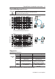
Status indicators:
“Status/Diag” LED illuminates Green Door/Guard closed, safety outputs active.
“Status/Diag” LED illuminates Red: Door/Guard open, safety outputs off.
“Status/Diag” LED flashes Red or Green Unit failure. See Diagnostic section below.
“Status/Diag” LED flashes Amber Sensor is approaching max. sensing distance.
PN-75056-179 ver 04 April 2012
SensaGuard
TM
Installation Instructions 3