
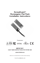
Installation Instructions Owner manual
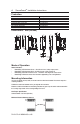
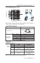
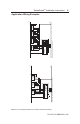

Sensing/Misalignment Curve
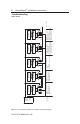
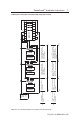
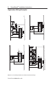
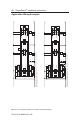
Typical Wiring Diagram
Description Plastic
8-Pin Micro (M12)
Grey Safety A
Red Safety A+
Pink Safety B
8-Pin Cordset Yellow Safety B+
889D-F8AB-* White Aux A
or cable version Brown 24V DC+
Blue Gnd / 0V
Green N/A
* Replace symbol with 2 (2m), 5 (5m) or 10 (10m) for standard cable lengths.
Diagnostic
Unit Indicators (per IEC 60073)
State Status Troubleshooting
Off Not Powered NA
Status/Diag Red Not Safe, OSSD not active NA
LED Green Safe, OSSD active NA
Green flash Power up test or OSSD Check 24V DC or OSSD inputs
inputs not valid (yellow and red wire)
Red Flash 1 Hz Flash Recoverable Fault Recoverable fault —check OSSD
4 Hz Flash Non-recoverable Fault outputs are not shorted to GND,
24V DC or each other. Cycle power.
Amber 1 Hz Flash margin indicator Sensor is reaching max. sensing
Flash safe, OSSD active distance; re-align sensor
with actuator
PN-114371 dir 10000182958 ver 00
SensaGuard
TM
Installation Instructions 5
2-24V DC+
1-Aux A
7-0V
6-Safet
y
B
3-N/A
8-Safety A+
4-Safety B+
5-Safety A
Note: Refer to Technical Specifications for Certification information and ratings.
0
5
10
15
20
25
30
35
Assured Make: 15mm
Assured OFF : 27mm
SIDE
LOBES
SIDE
LOBES
ASSURED
SENSING
DISTANCE
Sensing Distance (mm)
Note: There must be a minimum spacing of 9mm (0.35”) if the actuator and sensor face approaches
laterally.This will prevent false triggering due to the side lobes areas.