
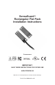
Installation Instructions Owner manual
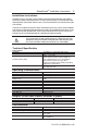
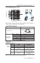

Protection
Short-Circuit Protection Incorporated
Current limitation Incorporated
Overload Protection Incorporated
False Pulse Protection Incorporated
Transient Noise Protection Incorporated
Reverse Polarity Protection Incorporated
Overvoltage protection Incorporated
Thermal shutdown/restart Incorporated
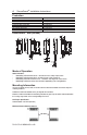
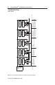
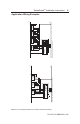
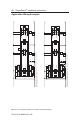
Dimensions - mm (inches)
Mode of Operation
Status indicators:
• “Status/Diag” LED illuminates Green - Door/Guard closed, safety outputs active.
• “Status/Diag” LED illuminates Red: - Door/Guard open, safety outputs off.
• “Status/Diag” LED flashes Red or Green: - Unit failure. See Diagnostic section below.
• “Status/Diag” LED flashes Amber when Sensor is approaching max. sensing distance.
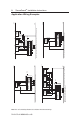
Mounting Information
Use non-removable screws, bolts, or nuts to mount the switch and actuator. Do not over torque the
mounting hardware.
Position the switch and actuator so they are aligned with each other.
Mount the switch and actuator to removable guard, door or gate. Keep the switch and actuator within
the sensing range shown in the sensing/misalignment curve.
Nut Torque Specification
Switch/Actuator: 2.26 N•M (20 in•lbs)
Minimum Distance Between Sensors
PN-114371 dir 10000182958 ver 00
4 SensaGuard
TM
Installation Instructions
24.99
(0.984)
88.14
(3.47)
10.66
(0.42)
7.11
(0.28)
6.78
(0.267)
4.57
(0.18)
¯ 5.08
(¯ 0.2))
4.57
(0.18)
68.31
(2.689)
18.54
(0.73)
72.9
(2.87)
77.98
(3.07)
20.65
(0.813)
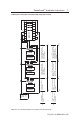
24.99
(0.984)
88.14
(3.47)
20.65
(0.813)
4.57
(0.18)
18.54
(0.73)
10.67
(0.42)
13.41
(0.528)
9.96
(0.392)
QD
CONNECTOR
VERSION
M12 x 1
¯ 9.7
(¯ 0.38)
4.57
(0.18)
¯ 5.08
(¯ 0.2)
4.57
(0.18)
77.98
(3.07)
62.53
(2.462)
57.96
(2.282)
82.55
(3.25)
200.00mm