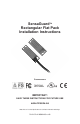
SensaGuardTM Rectangular Flat Pack Installation Instructions Certifications IMPORTANT: SAVE THESE INSTRUCTIONS FOR FUTURE USE 440N-Z21SS2H-AS Note: Refer to Technical Specifications for Certification information and ratings.
SensaGuardTM Installation Instructions This instruction sheet is available in multiple languages at www.rockwellautomation.com/literature. Select publication language and type "SensaGuard" in the search field. GERMAN: Dieses Instruktionsblatt kann in mehreren Sprachen unter www.rockwellautomation.com/literature gelesen werden. Bitte Ihre Sprache anwählen und "SensaGuard" im Suchfeld eintippen. FRENCH: Ces instructions sont disponibles dans différentes langues à l'adresse suivante www.rockwellautomation.
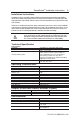
SensaGuardTM Installation Instructions 3 Installation Instructions Installation must be in accordance with the following steps and stated specifications and should be carried out by suitable competent personnel. The unit is not to be used as a mechanical stop. Guard stops and guides must be fitted. Adherence to the recommended maintenance instructions forms part of the warranty. This device is intended to be part of the safety related control system of a machine.
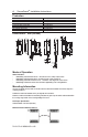
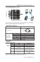
SensaGuardTM Installation Instructions 4 Protection Short-Circuit Protection Current limitation Overload Protection False Pulse Protection Transient Noise Protection Reverse Polarity Protection Overvoltage protection Thermal shutdown/restart Incorporated Incorporated Incorporated Incorporated Incorporated Incorporated Incorporated Incorporated Dimensions - mm (inches) 18.54 (0.73) 10.67 (0.42) 24.99 (0.984) 20.65 (0.813) 24.99 (0.984) 18.54 (0.73) 88.14 (3.47) 77.98 (3.07) 68.31 (2.689) 20.65 (0.
SensaGuardTM Installation Instructions 5 Sensing/Misalignment Curve SIDE LOBES ASSURED SENSING DISTANCE Sensing Distance (mm) 35 30 25 20 15 5 10 0 SIDE LOBES Assured Make: 15mm Assured OFF : 27mm Note: There must be a minimum spacing of 9mm (0.35”) if the actuator and sensor face approaches laterally.This will prevent false triggering due to the side lobes areas.
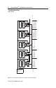
RTN PN-114371 dir 10000182958 ver 00 e +24 V +24 V W Blu e e Blu +0 V +0 V W Brown Gray Pink Red Yel Gray Pink Brown Red Yel Gray Pink Brown Red Yel Brown Gray Pink White Red Yel Blu e +0 V +0 V Actuator 5 is in sensing range. Switch 5 is functioning properl y . Series inputs are 0 V . OSSDs are de-energized to 0V. Green LED is Flashing to indicate Series inputs are not 24V. Yel Actuator 4 is in sensing range. Switch 4 is functioning properly . Series inputs are 0 V .
ON OFF Actuator 1 is out of sensing range. Actuator 2 and 3 are in sensing range. Initial Conditions: All actuators are in sensing distance. e Sensor 1 Actuator 1 0 ms Actuator 3 Actuator 2 378 ms Sensor 3 OSSD inputs (red and yellow) transition to 24V DC from Sensor 2 OSSD outputs. Sensor 3 OSSD outputs are energized. 396 ms 90 ms Pink Gray White Red Yel Sensor 3 drops the 24 volts (red and yellow) from Sensor 2 OSSD outputs. Green LED flashes.
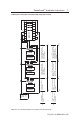
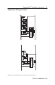
Pink Gray Blue PN-114371 dir 10000182958 ver 00 S22 S34 A2 24 K2 14 K1 23 41 42 33 34 Note: Refer to Technical Specifications for Certification information and ratings. S22 S34 A2 24 K2 K1 23 14 13 34 33 42 41 Reset GuardShield Brown Pink Gray Blue GND +24V DC GND MSR127RP with 3 sensors and 1 440L light curtain in series, monitored manual reset, driving 100S or 700S safety relays. Note: Light curtain must be last (farthest from MSR127).
S11 Pink Gray Blue A2 K1 14 K2 34 33 42 41 GND S11 S22 S34 S52 A2 S12 K1 14 13 K2 24 23 34 33 42 41 SensaGuard Unit 3 GuardShield Pink Gray Blue Brown Red Yellow Pink Gray Blue Brown Red Yellow GND +24V DC MSR127TP with 3 sensors and 1 440L light curtain in series, automatic reset, driving 100S or 700S safety contactors.
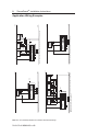
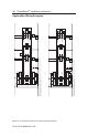
Brown Blue Gray Gray S62 Gray Pink Gray S42 S50 S62 S34 MSR211P 440R-H23177 SensaGuard S50 Pink SensaGuard Brown Red Yellow Brown Yellow Red Blue PN-114371 dir 10000182958 ver 00 K2 K1 Y2 Y3 K1 14 13 Brown Blue Note: Refer to Technical Specifications for Certification information and ratings.
Brown Yellow Red Blue Gray S50 Gray S62 SensaGuard Pink S42 MSR221P 440R-H23179 S32 Gray Gray SensaGuard Pink S42 S50 S62 S34 MSR211P 440R-H23177 Blue Red Yellow Brown Brown Yellow Red Blue MSR200 series with 4 sensors, automatic reset, driving 100S or 700S safety contactors.
SensaGuardTM Installation Instructions List of recommended relays MSR126, MSR127, MSR123, MSR124, MSR131, MSR138, MSR211, MSR121, MSR200 Family (Except MSR210), MSR300 Family, SmartGuard, 1791 DS DeviceNet™ Safety I/O. Relay must have light curtain inputs. Check the machine is isolated and stopped whenever the interlocked guard door is open.