
Owner manual

10. Application Wiring Examples
10.1
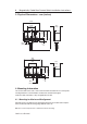
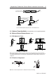
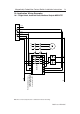
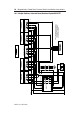
Single Switch, Automatic Reset, Monitored Outputs MSR127TP
72697 Issue 4 EO: 28485
Magnetically Coded Non Contact Switch Installation Instructions 9
Note: Refer to Technical Specifications for Certification information and ratings.
+24v
0v
Safety A+
Safety A-
Safety B+
Safety B-
Aux
Not
3313A1 S11 S12 23
S34 14A2 S21 S22 24
MSR127RP
+24V
0V
S52 41
34 42
K1
K2
L1
L2 L3
Brown (2)
Blue (7)
Red (8)
Grey (5)
Yellow (4)
Pink (6)
Green (3)
White (1)
MC2
Red
Grey
Pink
Yellow
Note: To maintain correct
diagnostic operation the
red wire (QD pin 8) must
be connected to S11.
Connected