
Owner manual
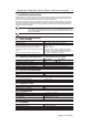

7. Connection Information
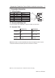
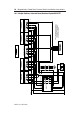
7.3
Connection Table
MSR100 family MSR200/300
Red/Safety A S11 S11
Grey/Safety A S12 S12 or S42
Yellow/Safety B S21 S21
Pink/Safety B S22 S22 or S52
Brown / +24V A1 / +24V A1 / +24V
Blue / 0V A2 / 0V A2 / 0V
Note: When the MC2 is used with any MSR100 series Relay for the diagnostic function to operate
correctly the Red and Grey wires (Safety A) must be connected to S11 and S12.
72697 Issue 4 EO: 28485
Magnetically Coded Non Contact Switch Installation Instructions 7
Note: Refer to Technical Specifications for Certification information and ratings.
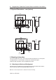
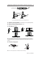
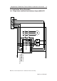
7.1
Wiring Diagram
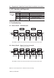
Pin # Wire Colour Signal
1 White PNP Aux
2 Brown +24V
3 Green Not connected
4 Yellow Safety B
5 Grey Safety A
6 Pink Safety B
7 Blue 0V
8 Red Safety A
7.2
Recommended Mating Cable
For 8-Pin micro (M12) option. 889D-F8AB-*. Lengths are available up to 30m (98.4 ft)
+24V
Aux
Gnd
Safety B
Safety A
Not
connected
Safety A
Safety B
4
7
6
8
1
5
2
3