Magnetically Coded Non Contact Switch (MC2) Installation Instructions 440N-Z21W1PA 3 Metre Cable 440N-Z21W1PB 10 Metre Cable 440N-Z21W1PH 8-Pin micro (M12) Pigtail Certifications IMPORTANT: SAVE THESE INSTRUCTIONS FOR FUTURE REFERENCE Note: Refer to Technical Specifications for Certification information and ratings.
Magnetically Coded Non Contact Switch Installation Instructions This instruction sheet is available in multiple languages at www.rockwellautomation.com/literature. Select publication language and type "SensaGuard" in the search field. GERMAN: Dieses Instruktionsblatt kann in mehreren Sprachen unter www.rockwellautomation.com/literature gelesen werden. Bitte Ihre Sprache anwählen und "SensaGuard" im Suchfeld eintippen.
Magnetically Coded Non Contact Switch Installation Instructions 3 1. Installation Instructions Installation must be in accordance with the following steps and stated specifications and should be carried out by suitable competent personnel. The unit is not to be used as a mechanical stop. Guard stops and guides must be fitted. Adherence to the recommended maintenance instructions forms part of the warranty. This device is intended to be part of the safety related control system of a machine.
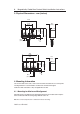
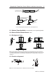
Magnetically Coded Non Contact Switch Installation Instructions 3. Physical Dimensions - mm (inches) 48.0 (1.89) 16.5 (0.65) 53 (2.1) 29.0 (1.14) 20.0 (0.79) 22.0 (0.87) 5.5 (0.22) Ø4.2 (0.17) 48.0 (1.89) 16.5 (0.65) Ø4.2 (0.17) 29.0 (1.14) 5.5 (0.22) 20.0 (0.79) 22.0 (0.87) 4. Mounting Information Use non-removable screws, bolts, or nuts to mount the switch and actuator. Do not over torque the mounting hardware. It is recommended to use M3 screws and washers throughout.
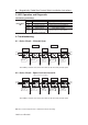
Magnetically Coded Non Contact Switch Installation Instructions To obtain maximum switching Actuator 5 Sensor distance center switches +/- 4mm To prevent damage it is recommended that a 2mm gap be maintained between the actuator and sensor To prevent damage it is recommended Actuator Actuator that a 2mm gap be maintained between the actuator and sensor Sensor Sensor To obtain maximum switching distance 8 - 14 mm distance 8 - 14 mm For more detailed misalignment characteristics refer to the misa
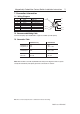
Magnetically Coded Non Contact Switch Installation Instructions 5. LED Operation and Diagnostic Unit Indicators (per IEC 60073) Device Output LED State Off Off Red Green Green flashing Status Troubleshooting Not Powered Check supply, check wiring to controller A Overload Check AUX connections Actuator not present If actuator present check misalignment.
Magnetically Coded Non Contact Switch Installation Instructions 7 7. Connection Information 7.1 Wiring Diagram Pin # 1 2 3 4 5 6 7 8 Wire Colour White Brown Green Yellow Grey Pink Blue Red Signal PNP Aux +24V Not connected Safety B Safety A Safety B 0V Safety A +24V Not connected Aux 1 2 3 7 8 4 Safety A 5 Gnd 6 Safety B Safety B Safety A 7.2 Recommended Mating Cable For 8-Pin micro (M12) option. 889D-F8AB-*. Lengths are available up to 30m (98.4 ft) 7.
Magnetically Coded Non Contact Switch Installation Instructions 8. Power Supply Requirements 24V dc +10%/-15% has to be supplied by a power supply that complies with IEC / EN 60204 and IEC / EN 61558-1. Such a power supply meets the electrical safety requirements and maintains the minimum power of 20.4V dc during 20ms even in the event of voltage dips. When using an approved Relay with an MC2 and the same power supply is utilised for all devices the Relay will provide surge protection for the MC2.
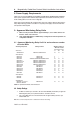
Magnetically Coded Non Contact Switch Installation Instructions 9 10. Application Wiring Examples 10.1 Single Switch, Automatic Reset, Monitored Outputs MSR127TP Not Connected Green (3) Safety BAux White (1) Pink (6) Yellow (4) Safety ASafety B+ Grey (5) Blue (7) 0v +24v 0V A2 S21 S22 S34 14 MSR127RP A1 S11 S52 S12 13 Red Note: To maintain correct diagnostic operation the red wire (QD pin 8) must be connected to S11.
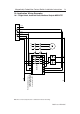
0V A2 S21 S22 S34 14 MSR127TP Red Grey Brown (2) Blue (7) 24 23 Red (8) +24v 0v Safety A+ 24 24 24 24 Safety ASafety B+ Pink (6) K2 K1 Pink L1 L2 L3 Grey Red Yellow +24v 0v Safety A+ S2 Safety ASafety B+ Safety BAux Not Connected Red Yellow Safety A+ Pink Grey Safety BAux White (1) Red Yellow Pink Grey Red Yellow MC2 S5 Actuator in place Flashing LED Green Note: To maintain diagnostic function the Red (QD pin 8) wire from the first switch (S1 in this example) must be co
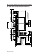
72697 Issue 4 EO: 28485 0V +24V Termination or Expansion Cable 24 A2 S11 S42 S52 S62 S21 Y30 Y32 Y33 S34 Y1 Y2 14 RESET 23 +24v 0v Safety A Safety A Safety B Yellow (4) Pink (6) Red (8) +24v 0v MC2 Y31 Y40 Y41 Y42 13 A1 S41 S22 S32 S12 S51 Blue (7) MC2 Brown (2) Red (8) Grey (5) Safety B Aux White (1) Not Green (3) Connected Brown (2) Blue (7) Safety A Grey (5) Safety A Fuses Yellow (4) Safety B Pink (6) 32 31 White (1) Safety B Aux Not Green (3) Connected Termination or E
Magnetically Coded Non Contact Switch Installation Instructions Check the machine is isolated and stopped whenever the interlocked guard door is open. IMPORTANT: After installation and commissioning, the actuator, switch and hardware should be coated with tamper evident varnish or similar compound. 11. Maintenance Every six months Check the correct operation of the switching circuit. Also check for signs of abuse or tampering. Inspect the switch casing for damage. 12.