
Installation Instructions Owner's manual


8 SensaGuard
TM
Installation Instructions
Note: Refer to Technical Specifications for Certification information and ratings.Note: Refer to Technical Specifications for Certification information and ratings.
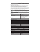
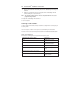
Diagnostic
Unit Indicators (per IEC 60073)
State Status Troubleshooting
Off Not Powered NA
Status/Diag Red Not Safe, OSSD not active NA
LED Green Safe, OSSD active NA
Green flash Power up test or OSSD Check 24V DC or OSSD inputs
inputs not valid (yellow and red wire)
Red Flash 1 Hz Flash OSSD Fault OSSD fault —check OSSD
4 Hz Flash Recoverable / outputs are not shorted to GND,
Non-recoverable Fault 24V DC or each other. Cycle power.
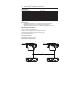
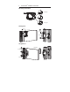
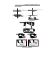
Typical Wiring Diagram
Description Plastic
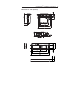
8-Pin Micro (M12)
Grey Safety A
Red Safety A+
Pink Safety B
8-Pin Cordset Yellow Safety B+
889D-F8AB-* White Aux A
or cable version Brown 24V DC+
Blue 0V
Green N/A
* Replace symbol with 2 (2m), 5 (5m) or 10 (10m) for standard cable lengths.
2-24V DC+
1-Aux A
7-0V
6-Safet
y
B
3-N/A
8-Safety A+
4-Safety B+
5-Safety A