
Installation Instructions Owner's manual


Protection
Short-Circuit Protection Incorporated
Current limitation Incorporated
Overload Protection Incorporated
False Pulse Protection Incorporated
Transient Noise Protection Incorporated
Reverse Polarity Protection Incorporated
Overvoltage protection Incorporated
Thermal shutdown/restart Incorporated
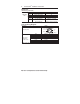
Electrical Life 10 x 10
6
Mode of Operation
Status indicators:
• “Status/Diag” LED illuminates Green - Door/Guard closed, safety outputs active.
• “Status/Diag” LED illuminates Red: - Door/Guard open, safety outputs off.
• “Status/Diag” LED flashes Red or Green: - Unit failure. See Diagnostic section below.
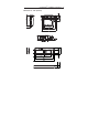
Mounting Information
Do not over torque the mounting hardware.
Position the switch and actuator so they are aligned with each other.
Mount the switch and actuator to removable guard, door or gate.
Recommended fastener size - M6
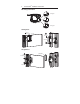
Nut Torque Specification
Switch/Actuator: 2.20 N·M (19.5 in·lbs)
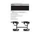
Minimum Distance Between Sensors
4 SensaGuard
TM
Installation Instructions
mm188