
Installation Instructions Owner's manual


12 SensaGuard
TM
Installation Instructions
Note: Refer to Technical Specifications for Certification information and ratings.
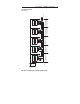
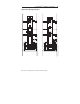
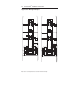
Unit Response Time (does not include safety relay response time)
Yel
Red
White
Gray
Pink
Blue
24V DC
Power
Supply
1606
Sensor 1
+24
RT
Sensor 2
Brown
Brown
Gray
Pink
White
Yel
Red
Blue
Sensor 3
Brown
Yel
Red
White
Gray
Pink
Blue
A1
S21
S11 41332313S12S52
42342414A2S34S22
440R-N23127
Actuator 1
Actuator 2
Actuator 3
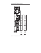
Initial Conditions:
All actuators are in sensing
distance.
Actuator 1 is moved out of
sensing range.
Sensor 2 drops the 24 volts
(red and yellow) from Sensor 1
OSSD outputs.
Green LED flashes.
Sensor 3 drops the 24 volts
(red and yellow) from Sensor 2
OSSD outputs.
Green LED flashes.
0 ms
54 ms 72 ms 90 ms
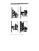
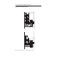
Actuator 1 is out of sensing
range.
Actuator 2 and 3 are in
sensing range.
Actuator 1 is moved into sensing
range.
Sensor 1 OSSD outputs are
energized.
Sensor 2 OSSD inputs (red and yellow)
transition to 24V DC from Sensor 1
OSSD outputs.
Sensor 2 OSSD outputs are energized
Sensor 3 OSSD inputs (red and
yellow) transition to 24V DC from
Sensor 2 OSSD outputs.
Sensor 3 OSSD outputs are
energized.
0 ms
360 ms 378 ms 396 ms
OFF
ON