
Installation Instructions Manual

PN-46046 10000054880 Ver 00 October 2009
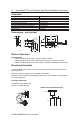
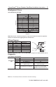
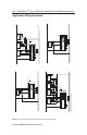
Misalignment Curve
18 mm Unit with 18 mm Target
Note: There must be a minimum spacing of 4 mm (0.157 in) if actuator and sensor face approaches
laterally. This will prevent false triggering due to the side lobe areas.
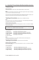
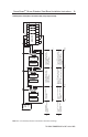
Wiring Diagram
Pin # Wire Color Signal
1 White Aux Outputs
2 Brown +24V
3 Green Sheild
4 Yellow OSSD 2, +24V Input
5 Grey OSSD 1
6 Pink OSSD 2
7 Blue 0V
8 Red OSSD 1, +24V Input
Recommended mating cable, 2 m (6.5 ft). 889D-F8AB-2. Lengths are available up to 30 m (98.4 ft)
Diagnostic
Unit Indicators (per IEC 60073)
State Status Troubleshooting
Off Not Powered NA
Device Output Red Not Safe, OSSD not active NA
LED Green Safe, OSSD active NA
Green flash Power up test or OSSD Check 24V DC or OSSD inputs
inputs not valid (yellow and red wire)
Red Flash 1 Hz Flash Recoverable Fault Recoverable fault —check OSSD
4 Hz Flash Non-recoverable Fault outputs are not shorted to GND,
24V DC or each other. Cycle power.
SensaGuard
TM
18 mm Stainless Steel Barrel Installation Instructions 5
Misalignment
Sensing Distance
0
1
2
3
4
5
6
7
8
9
10
11
12
13
14
15
-15-14-13-12-11-10-9 -8 -7 -6 -5 -4 -3 -2 -1 0 1 2 3 4 5 6 7 8 9 10 1112 13 1415
Side Lobe Side Lobe
Assured Sensing
Distance
OFF OFF
OFF
ON
4
7
6
8
1
5
2
3
Brown
White
Blue
Pink
Grey
Green
Red
Yellow
Note: Refer to Technical Specifications for Certification information and ratings.