
Installation Instructions Manual
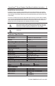

Protection
Short-Circuit Protection Incorporated
Current limitation Incorporated
Overload Protection Incorporated
False Pulse Protection Incorporated
Transient Noise Protection Incorporated
Reverse Polarity Protection Incorporated
Overvoltage protection (inc. load dump) Incorporated
Thermal shutdown/restart Incorporated
Electrical Life 10 x 10
6
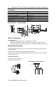
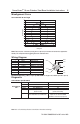
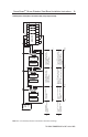
Dimensions - mm (inches)
Mode of Operation
Status indicators:
• “Power/Fault” LED illuminates Green -
The unit is ready for operation.
• “Power/Fault” LED illuminates Red: -
Door/Guard open. The unit is not ready for operation.
• “Power/Fault” LED illuminates flashes Red or Green: -
Unit failure. See Diagnostic section below.
Mounting Information
Use non-removable screws, bolts, or nuts to mount the switch and actuator. Do not over torque the
mounting hardware.
Position the switch and actuator so they are aligned with each other.
Mount the switch and actuator to removable guard, door or gate. Keep the switch and actuator within
the sensing range below.
Nut Torque Specification
Barrel Switch: 2.26 N•M (20 in•lbs)
Actuators: 2.26 N•M (20 in•lbs)
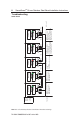
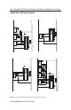
Minimum Distance Between Sensors
PN-46046 10000054880 Ver 00 October 2009
4 SensaGuard
TM
18 mm Stainless Steel Barrel Installation Instructions
14.43
(0.568)
4.75
(0.187)
16.1
(0.634)
4.57
(0.18) Dia.
2 Places
15.87
(0.625)
13.72
(0.54)
36.47
(1.436)
13.72
(0.54)
15.87
(0.625)
36.47
(1.436)
Actuator
13.9
(0.547)
15.87
(0.625)
74.7
(2.94)
10.4
(0.409)
44.5
(1.75)
16.4
(0.436)
M18 x 1
Sensor
18 mm Actuator
50 mm
Sensor
1
Sensor
2