SensaGuardTM 18 mm Plastic Barrel Unique Coded Installation Instructions Certifications IMPORTANT: SAVE THESE INSTRUCTIONS FOR FUTURE USE Note: Refer to Technical Specifications for Certification information and ratings.
SensaGuardTM 18 mm Plastic Barrel Installation Instructions This instruction sheet is available in multiple languages at www.rockwellautomation.com/literature. Select publication language and type "SensaGuard" in the search field. GERMAN: Dieses Instruktionsblatt kann in mehreren Sprachen unter www.rockwellautomation.com/literature gelesen werden. Bitte Ihre Sprache anwählen und "SensaGuard" im Suchfeld eintippen.
SensaGuardTM 18 mm Plastic Barrel Installation Instructions 3 Installation Instructions Installation must be in accordance with the following steps and stated specifications and should be carried out by suitable competent personnel. The unit is not to be used as a mechanical stop. Guard stops and guides must be fitted. Adherence to the recommended maintenance instructions forms part of the warranty. This device is intended to be part of the safety related control system of a machine.
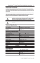
SensaGuardTM 18 mm Plastic Barrel Installation Instructions Protection Short-Circuit Protection Current limitation Overload Protection False Pulse Protection Transient Noise Protection Reverse Polarity Protection Overvoltage protection Thermal shutdown/restart Electrical Life Incorporated Incorporated Incorporated Incorporated Incorporated Incorporated Incorporated Incorporated 10 x 106 Dimensions - mm (inches) 16.84 [0.663] 3.17 [0.125] 4.57 [0.18] DIA 2 PLACES 48.92 [1.926] 30.40 [1.197] 22.
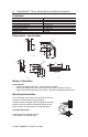
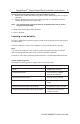
SensaGuardTM 18 mm Plastic Barrel Installation Instructions 5 Minimum Distance Between Sensors 18 mm Actuator 30 mm Actuator 75 mm 100 mm Sensor 1 Sensor 1 Sensor 2 Sensor 2 Misalignment Curve 18 mm Unit with 18 mm Target 18 mm Unit with 30 mm Target 35 25 30 OFF OFF 15 Assured Sensing Distance 10 ON 5 Side Lobe Side Lobe 0 -25 -20 -15 -10 -5 (-0.98)(-0.787)(-0.59) (-0.39)(-0.19) 0 5 10 15 20 25 (0.19) (0.39) (0.59) (0.787) (0.
SensaGuardTM 18 mm Plastic Barrel Installation Instructions 6 Commissioning Power the Sensor Connect the sensor to 24Vdc. See "Typical Wiring Diagram" section for help. Note: The sensor "Status/Diag" LED will begin to blink Green eight times then repeat, indicating that the sensor has not yet learned an actuator. The sensor can be commissioned to either have the ability to learn another actuator or be locked for a one time learn only. See ‘Teaching in the actuator’ section.
SensaGuardTM 18 mm Plastic Barrel Installation Instructions 7 During the Program Locking Stage, perform the following steps: a. Remove the actuator from the sensing field, until the "Status/Diag" LED changes to solid Red. b. Replace the actuator back into the sensing field and the "Status/Diag" LED will continue blinking Green (# of learns left). Note: The program locking sequence must be completed within the 15 second program locking window. 5. Ready state: "Status/Diag" LED solid Green 6.
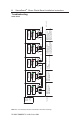
RTN e +24 V +24 V W PN-46045 10000054879 Ver 00 October 2009 Blu e e Blu +0 V +0 V W Brown Gray Pink Red Yel Gray Pink Brown Red Yel Gray Pink Brown Red Yel Brown Gray Pink White Red Yel Blu e +0 V +0 V Actuator 5 is in sensing range. Switch 5 is functioning properl y . Series inputs are 0 V . OSSDs are de-energized to 0V. Green LED is Flashing to indicate Series inputs are not 24V. Yel Actuator 4 is in sensing range. Switch 4 is functioning properly . Series inputs are 0 V .
Initial Conditions: All actuators are in sensing distance. Actuator 1 is out of sensing range. Actuator 2 and 3 are in sensing range. OFF ON e Sensor 1 Actuator 1 0 mS Actuator 3 Actuator 2 378 mS Sensor 3 OSSD inputs (red and yellow) transition to 24V DC from Sensor 2 OSSD outputs. Sensor 3 OSSD outputs are energized. 396 mS 90 mS Pink Gray White Red Yel Sensor 3 drops the 24 volts (red and yellow) from Sensor 2 OSSD outputs. Green LED flashes.
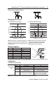
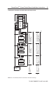
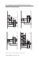
Pink Gray Blue S22 S34 A2 24 K2 14 K1 23 41 42 33 34 PN-46045 10000054879 Ver 00 October 2009 Note: Refer to Technical Specifications for Certification information and ratings. S22 S34 A2 24 K2 K1 23 14 13 34 33 42 41 Reset GuardShield Brown Pink Gray Blue GND +24V DC GND MSR127RP with 3 sensors and 1 440L light curtain in series, monitored manual reset, driving 100S or 700S safety relays. Note: Light curtain must be last (farthest from MSR127).
S11 Brown Pink Gray Blue A2 24 K2 14 K1 34 42 41 GND S11 S22 S34 S52 A2 S12 24 K2 K1 23 14 13 34 33 42 41 SensaGuard Unit 3 GuardShield Pink Gray Blue Brown Red Yellow Pink Gray Blue Brown Red Yellow GND +24V DC MSR127TP with 3 sensors and 1 440L light curtain in series, automatic reset, driving 100S or 700S safety contactors.
Brown Blue Gray Gray S62 Gray Pink Gray S42 S50 S62 S34 MSR211P 440R-H23177 SensaGuard S50 Pink SensaGuard Brown Red Yellow Brown Yellow Red Blue K2 K1 Y2 Y3 K1 14 13 PN-46045 10000054879 Ver 00 October 2009 Brown Blue Note: Refer to Technical Specifications for Certification information and ratings.
Brown Yellow Red Blue Gray S50 Gray S62 SensaGuard Pink S42 MSR221P 440R-H23179 S32 Gray Gray SensaGuard Pink S42 S50 S62 S34 MSR211P 440R-H23177 Blue Red Yellow Brown Brown Yellow Red Blue MSR200 series with 4 sensors, automatic reset, driving 100S or 700S safety contactors.
SensaGuardTM 18 mm Plastic Barrel Installation Instructions List of recommended relays MSR126, MSR127, MSR123, MSR124, MSR131, MSR138, MSR211, MSR121, MSR320, MSR200 Family (Except MSR210), MSR300 Family, SmartGuard, 1791 DS DeviceNet™ Safety I/O. Relay must have light curtain inputs. Check the machine is isolated and stopped whenever the interlocked guard door is open.