
Safety Interface M8200 Relay Module Owner's manual

81
75035-119-01(A) / K832 / 26-09-00 © Rockwell Automation • Milwaukee, Wisconsin • All rights reserved
Operating instructions
M 8200
GB
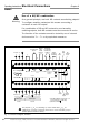
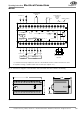
Fig. 2: Connection diagram of the M 8200 with command unit and contactor monitoring
Electrical Connections
Chapter 4
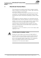
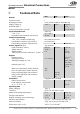
Fig. 3: Dimensions, M 8200
152
118
35
70
*) If Sensors with relay outputs are used or if the M 8200 and the contact elements are used
in separate housing, a suitable cable must be laid (see chapter 2.1.).
24 V DC 0 V
24 V DC
0 V
24 V DC 0 V
OSSD
1
OSSD
2
N
K 1 K 2
K 1
K 2
*)
Auxiliary contacts
0 V
0 V
24 V DC 24 V DC0 V
on
outputs
off
24 V DC 0 V
Power Input
Sender Receiver
Reset
Contactors
Monitor Ext.
auto
offcontacts
24 V DC 0 V
24 V DC 0 V
A
1
+A
2
–PE T
0
PE T
13
T
14
X
11
X
12
T
21
T
22
X
21
X
22 1.3 2.3 3.1
C
1
D
1
PE C
2
D
2
PE T
3
T
4
C
3
D
3
PE C
4
D
4 1.4 2.4 3.2
N.C.
N.O.
N.O.
AOPD type 4
AOPD type 4
sender receiver
Command unit
„Reset“
Control voltage of
contactors
or to stop
circuit
To the contactors or to
stop circuit