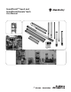
GuardShield™ Type 4 and GuardShield Remote Teach User Manual
Important User Information Because of the variety of uses for the products described in this publication, those responsible for the application and use of this control equipment must satisfy themselves that all necessary steps have been taken to assure that each application and use meets all performance and safety requirements, including any applicable laws, regulations, codes and standards.
GuardShield™ Safety Light Curtain User Manual Conditions required for proper use of the GuardShield Safety Light Curtain Please make sure you read and understand these requirements before you select and install the GuardShield safety light curtain. GuardShield safety light curtains are point of operation safeguarding devices. These safety light curtains are intended to be used to provide point of operation safeguarding of personnel on a variety of machinery.
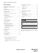
GuardShield™ Safety Light Curtain User Manual Table of Contents Safety Instructions—Maintenance . . . . . . . . . . . . . . . . . 21 GuardShield Safety Light Curtain . . . . . . . . . . . 3 Introduction . . . . . . . . . . . . . . . . . . . . . . . . . . . . . . . . . . . . 3 Safety Precautions. . . . . . . . . . . . . . . . . . . . . . . . . . . . . . . . 3 Daily Inspection . . . . . . . . . . . . . . . . . . . . . . . . . . . . . . . . . . . . . . Six-month Inspection . . . . . . . . . . . . . . . . .
GuardShield™ Safety Light Curtain User Manual GuardShield Safety Light Curtain Safety Precautions Introduction Principles for Safe Use and Symbols Used The GuardShield family of safety light curtains are general purpose presence sensing devices, designed for use on hazardous machinery providing point of operation, as well as, perimeter and access detection. It is a self-contained, two box, Type 4 ESPE (Electro Sensitive Protective Equipment) with DIP-switch selectable operating modes.
GuardShield™ Safety Light Curtain User Manual Specialist Personnel The GuardShield safety light curtain must be installed, commissioned and serviced only by a qualified person.
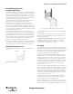
GuardShield™ Safety Light Curtain User Manual GuardShield Light Curtain Principle of Operation The GuardShield safety light curtain consists of a non-matched pair of optic units, i.e., transmitter and receiver with the same protected height and resolution. The transmitter and receiver operate on +24V DC. The maximum distance between transmitter and receiver is referred to as the protective field width or range. The protective field height is the distance between the first and last beam in the device.
GuardShield™ Safety Light Curtain User Manual possible to use a standard GuardShield Type 4 POC pair as the last segment in a cascading system. IMPORTANT The protective system must be tested for proper operation after each and every change to the configuration. Examples of Range of Use The GuardShield safety light curtain operates as a proper protective device only if the following conditions are met: • The control of the machine must be electrical.
GuardShield™ Safety Light Curtain User Manual EDM is not available in the middle and end segments of a cascading GuardShield system, however, it is possible to configure this operating mode in the host segment allowing the whole cascading system to operate in this mode. External Device Monitoring (EDM) is not available in GuardShield light curtains with ArmorBlock Guard I/O connectivity.
GuardShield™ Safety Light Curtain User Manual Fixed Blank Beam Roller Work Path IMPORTANT Actuation of the floating blanking mode of operation changes the resolution of the GuardShield. GuardShield Resolution 14 mm (0.55 in.) 30 mm (1.18 in.) Work Piece Number of Beams “Floated” Effective Resolution 1 Beam 24 mm (0.94 in.) 2 Beam 34 mm (1.34 in.) 1 Beam 50 mm (1.97 in.
GuardShield™ Safety Light Curtain User Manual IR Beam Floating Blanking Deactivated Floating Blanking 1 Channel Active Floating Blanking 2 Channels Active 1 2 3 4 5 Machine Stop On On Stop Stop On On Response Time IMPORTANT The response time of the GuardShield safety light curtain depends on the height of the protective field, the resolution and the number of light beams as well as the coding of the system.
GuardShield™ Safety Light Curtain User Manual OSHA Safety Distance Calculation Formula The OSHA safety distance formula as specified in CFR Subpart O 1910.217 is as follows: Ds = 63 X TS Ds Safety Distance 63 Is the OSHA recommended hand speed constant in inches per second Ts Is the total stop time of all devices in the safety circuit, measured in seconds. This value must include all components involved in stopping the hazardous motion of the machinery.
GuardShield™ Safety Light Curtain User Manual If the result S is > 500 mm (19.6 in.), then recalculate S as follows: S = 1600 × T + 8 × (d – 14) [mm] If the new value S is > 500 mm (19.6 in.), then use the newly determined value as the minimum safety distance. If the new value S is ≤ 500 mm (19.6 in.), then use 500 mm (19.6 in.) as the safety distance. Example: Stopping/run-down time of the machine = 290 ms Response time = 30 ms Resolution of the light curtain = 14 mm (0.55 in.
GuardShield™ Safety Light Curtain User Manual Cycle power to assure that the system powers up and goes to the ON state (alignment indicator is OFF). Correct Installation The GuardShield is also offered with an integrated laser alignment system which has a constantly powered Class 1, eye safe laser located in the top of the GuardShield transmitter and in the bottom of the GuardShield receiver. Each laser emits a low level of visible light.
GuardShield™ Safety Light Curtain User Manual Middle of Depth of Protective Field Point of Operation Safety Distance Top of tool Machine stop time The next step is to select the interconnect patchcords for the transmitter and receiver. These patchcords are offered in a variety of lengths. Finally it is necessary to determine if the last segment of the cascading system is a standard or cascading GuardShield pair.
GuardShield™ Safety Light Curtain User Manual Transmitters emit in opposite direction. Each receiver receives only the beams of the appropriate transmitter. Transmitters emit in same direction: ➡Coding necessary Noncoded Coded Positioning of the light curtain: Transmitters emit in opposite direction.
GuardShield™ Safety Light Curtain User Manual Optional Middle Mounting Bracket (440L-AF6108) 30 (1.18) 20 (0.78) 49.2 (1.93) • The grounded conductor of the power supply device must be connected to a grounded conductor PE. • The maximum deviation of the voltage levels is 24V DC +/20%. Double insulation 62 (2.44) 40.2 (1.58) Basic insulation (See note.) Output (pink and grey) Guard Shield Basic insulation This part of the insulation provides supplementary insulation against hazardous voltage levels.
GuardShield™ Safety Light Curtain User Manual Not available for GuardShield with ArmorBlock Guard I/O connectivity. IMPORTANT Connections [mm (in.)] Cat. No. Description Transmitter Patchcord 889D-F4HLDM-0M3 4-pin M12 patchcord, 12 inches 889D-F4HLDM-1 4-pin M12 patchcord, 1 meter 889D-F4HLDM-2 4-pin M12 patchcord, 2 meters 42 (1.7) Receiver Patchcords 15 (0.
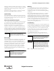
GuardShield™ Safety Light Curtain User Manual Typical Wiring Diagram—Direct to Contactors + 24V DC SENDER S2 Start/Restart RECEIVER Brown Brown Red Gray L1 OSSD 1 K2 S1 Test Machine Test Signal L2 L3 Pink Bulletin 100S Safety Contactors or 700S Safety Relays OSSD 2 Black K1 MPCE/EDM Yellow White M Blue Blue Auxiliary Signal Green 24V Ground Nonsafety auxiliary output can be connected to a lamp, motor or status to a PLC.
GuardShield™ Safety Light Curtain User Manual System Configuration When delivered from the factory, the following settings are configured. DIP-Switch Selection Settings—Transmitter Door Status Switch Receiver—Factory Settings Switch 1 ON 3 MPCE Monitoring disable ON Disabled 4 Fixed Blanking Activate OFF Disabled 5 Floating Blanking Activate—Single Beam OFF Switches 5&6 cannot be activated “On” at the same time.
GuardShield™ Safety Light Curtain User Manual Cascading segment’s DIP switch settings There are a few operating modes that can not be configured in the middle and end segments of a cascading GuardShield system. The following Operating modes if configured will cause the light curtain to fault; • EDM (External Device Monitoring) • Start and Restart Interlock Power must be cycled and the segment pair must be re-taught to deactivate the mode.
GuardShield™ Safety Light Curtain User Manual System Status Indicators Receiver Transmitter OSSDs OFF Blanking Emitting OSSDs ON Alignment POWER ON Interlock Receiver LEDs OSSDs OFF Condition No.
GuardShield™ Safety Light Curtain User Manual ATTENTION IMPORTANT Assure that all power to the machine, and safety system is disconnected during electrical installation. Prior to powering up the GuardShield system, the responsible person should review the following Checklist. Safety Instructions—Maintenance ATTENTION Never operate the GuardShield before carrying out the following inspection. Improper inspection can lead to serious or even deadly injury. Note: 1.
GuardShield™ Safety Light Curtain User Manual Date Code Bul/Type Ref No. Receiver Ambient Temp Ser Rev Power Consumption A A F4J0320YD Part No. Transmitter 440L -10.....+55C 7W max. Supply Voltage 24V DC +/-20% Made in Jun, 2010 Safety Parameters Type 4/Cat.4 IEC61496/ EN ISO 13849 EN62061/ IEC61508 AA00AA00 Operating Instructions PLe/SIL CL3,SIL3 PN-20857 GuardShield Rockwell Automation 2 Executive Dr. Chelmsford MA.
GuardShield™ Safety Light Curtain User Manual Technical Specifications Light Beams 8 – 176 Protective Field 160…1760 mm (6.3…69.29 in.) in 160 mm (6.3 in.) increments for Standard GuardShield; 320…1600 mm for GuardShield with Integrated Laser Alignment Resolution 14 mm (0.55 in.), 30 mm (1.18 in.) Range 14 mm (0.55 in.); 0.3…7.0 m (0.98…22.9 ft), 30 mm (1.18 in.); 0.3…18.0 m (0.98…59.
GuardShield™ Safety Light Curtain User Manual Standard GuardShield Sensor Pair Transmitter Receiver Resolution [mm (in.)] No. of Beams Protective Heights [mm (in.)] Pair Weight [kg (lbs)] 440L-P4J0160YD 440L-T4J0160YD 440L-R4J0160YD 14 (0.55) 440L-P4J0320YD 440L-T4J0320YD 440L-R4J0320YD 14 (0.55) 16 160 (6.3) 3.15 (1.43) 32 320 (12.59) 5.17 (2.35) 440L-P4J0480YD 440L-T4J0480YD 440L-R4J0480YD 14 (0.55) 48 480 (18.89) 6.59 (2.99) 64 640 (25.19) 7.99 (3.62) 80 800 (31.49) 9.
GuardShield™ Safety Light Curtain User Manual Standard GuardShield with Integrated Laser Alignment and ArmorBlock I/O Connection Sensor Pair Transmitter Receiver Resolution [mm (in.)] No. of Beams Protective Heights [mm (in.)] Pair Weight [kg (lbs)] 440L-P4JL0320YA 440L-T4JL0320YA 440L-R4JL0320YA 14 (0.55) 32 320 (12.59) 5.17 (2.35) 440L-P4JL0480YA 440L-T4JL0480YA 440L-R4JL0480YA 14 (0.55) 48 480 (18.89) 6.59 (2.99) 440L-P4JL0640YA 440L-T4JL0640YA 440L-R4JL0640YA 14 (0.
GuardShield™ Safety Light Curtain User Manual Cascading GuardShield with Integrated Laser Alignment Sensor Pair Transmitter Receiver Resolution [mm (in.)] No. of Beams Protective Heights [mm (in.)] Pair Weight [kg (lbs)] 440L-C4JL0320YD 440L-G4JL0320YD 440L-F4JL0320YD 14 (0.55) 32 320 (12.59) 5.17 (2.35) 440L-C4JL0480YD 440L-G4JL0480YD 440L-F4JL0480YD 14 (0.55) 48 480 (18.89) 6.59 (2.99) 440L-C4JL0640YD 440L-G4JL0640YD 440L-F4JL0640YD 14 (0.55) 64 640 (25.19) 7.99(3.
GuardShield™ Safety Light Curtain User Manual Cat. No. Explanation—Standard and Cascading GuardShield without Laser Alignment System 440L - P 4 J 03 20 Y D Connector Option Micro QD R-Remote Teach Pigtail Connector A-ArmorBlock Safety I/O Connector (M12, 5 pin Environmental Rating IP65 0160 - Protective Height 0320 0480 0960 1440 0640 1120 1600 0800 1280 1760 14 mm (0.55 in.) GuardShield K - 30 mm (1.18 in.
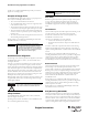
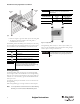
GuardShield™ Safety Light Curtain User Manual Dimensions [mm (in.)] 42 (1.65) 20 (0.79) 52 (2.05) 52 (2.05) 11 (0.43) 32 (1.25) 11 (0.43) 80 (3.14) min. 40 (1.57) To be used in vibration applications C B A 75 (2.95) 80 (3.14) min. 80 (3.14) min. Standard A Protective Height B Mounting Value C Total Length 440L-40160Y 160 ±0.5 (6.3) ±0.02 276 (10.9) 312 ±1.5 (12.3) ±0.06 440L-40320Y 320 ±0.5 (12.6) ±0.02 436 (17.2) 472 ±1.5 (18.6) ±0.06 440L-40480Y 480 ±0.5 (18.9) ±0.
GuardShield™ Safety Light Curtain User Manual 80 (3.14) min. 11 (0.48) 440L-R4JL0320YD shown receiver 42 (1.65) A Middle mounting bracket to be used in vibration applications 40 (1.57) 75 (2.95) 52 (2.05) 40 20 (0.79) (1.57) B C 440L-T4JL0320YD shown transmitter 440L-P4JL0320YD shown K = 30 mm resolution J = 14 mm resolution L = Laser 63.5 (2.50) D 80 (3.14) min. 80 (3.14) min. 11 (0.48) 42 (1.65) 440L-F4JL0320YD shown receiver A 40 (1.
GuardShield™ Safety Light Curtain User Manual GuardShield Remote Teach System Delivery Introduction The GuardShield Remote Teach system is delivered with the GuardShield transmitter and receiver configured in the standard GuardShield operating mode of “Guard Only,” which is Automatic reset, and all features not activated. The GuardShield Remote Teach system provides a remote means of changing a fixed blanking configuration within the GuardShield safety light curtain.
GuardShield™ Safety Light Curtain User Manual Note: If the Transmitter’s configuration needs to be changed from the factory settings, set the DIP switches in the transmitter and follow the standard teach process Remote Teach System Cat. No.
GuardShield™ Safety Light Curtain User Manual Remote Teach Receiver Catalog Number 32 Dimensions [mm (in.)] 127 (5) Description 101.
GuardShield™ Safety Light Curtain User Manual Optional Accessories Description Cat. No. Steel L-shaped end cap mounting bracket (4 per package) Note: 4 brackets supplied with each GuardShield pair.
GuardShield™ Safety Light Curtain User Manual Mirror 440L-AM075 Mirror 440L-AM125 8 x 13 Section A 44.4 75 (174) (2.65) 164 (6.45) "Z" 50 (1.96) 35 (1.37) 54 (2.12) 13.3 (0.52) 6.5 (0.25) 73 (2.87) "Z" 4.5 (0.17) 10.5 (0.41) 164 (6.45) 50 (1.96) A B L ±120° 2.5 (0.09) A A Ls L 396 (15.60) Ls 340 (13.4) A 372 (14.64) B 440 (17.32) 10.5 (0.41) A 4.5 (0.17) 2.5 (0.09) A 6.5 (0.25) Section A-A +/- 120° 13.3 (5.24) 35 (1.37) 123 (4.84) 54 (2.12) 44.4 (1.74) 75 (2.95) 50 (1.
GuardShield™ Safety Light Curtain User Manual Corner Mirror for Multi-Sided Guarding Specially constructed glass mirrors for 2- and 3-sided safeguarding applications. Note: Each mirror reduces maximum scan range by 10% per mirror. Each corner mirror suppled with two end-cap mounting brackets. GuardShield Light Curtain Cat. No. Narrow Mirror Short-Range 0…4 m Cat. No. Wide Mirror Long-Range 4…15 m Cat. No.
GuardShield™ Safety Light Curtain User Manual Weld Shields Signal The GuardShield weld shields are sold as pairs in the same lengths as the protective heights of the GuardShield safety light curtain. These polycarbonate weld shields are designed as disposable devices whose purpose is to protect the front window of the GuardShield from damage. Top View 2 3 8 1 4 Dimensions [mm (in.)] 7 5 6 3.0 (0.118) Thick 37.3 (1.47) 49.5 (1.95) R24 2X L Color Pin No.
GuardShield™ Safety Light Curtain User Manual For Connection to Transmitter Interconnecting Patchcords— ArmorBlock I/O Connection Cat. No. Cat. No. Description 889D-F5ACDM-0M3 5 pin M12 patchcord, 12 inches 889D-F5ACDM-1 5 pin M12 patchcord, 1 meter 889D-F5ACDM-2 5 pin M12 patchcord, 2 meters 889D-F5ACDM-5 6 pin M12 patchcord, 5 meters 889D-F5ACDM-10 7 pin M12 patchcord, 10 meters Note: Transmitter and receiver use same five-pin patchcords. Select one cat. no. for each.
GuardShield™ Safety Light Curtain User Manual EC Declaration of Conformity The undersigned, representing the manufacturer Rockwell Automation, Inc.
GuardShield™ Safety Light Curtain User Manual Catalogue number Series 1 Description 440L-*4***** GuardShield Type4 light curtains per Nomenclature 1) If no series number is given, then all series are covered MODEL NOMENCLATURE: 440L 1 1 2 3 4 5 6 7 8 - P 2 4 3 J 4 L 5 1600 6 Y 7 D 8 Designates Product Type 440L – GuardShield safety light curtains Light Curtain Type P – Transmitter/receiver pair C – Cascaded sensor pair R – Receiver F – Cascaded receiver T – Transmitter G – Cascaded transmi
GuardShield™ Safety Light Curtain User Manual 40 Original instructions R
GuardShield™ Safety Light Curtain User Manual 40 Original instructions R
GuardShield is a trademark of Rockwell Automation, Inc. www.rockwellautomation.com Power, Control and Information Solutions Headquarters Americas: Rockwell Automation, 1201 South Second Street, Milwaukee, WI 53204 USA, Tel: (1) 414.382.2000, Fax: (1) 414.382.