
Manual

5
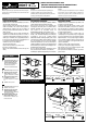
Check the machine is isolated and stopped
whenever the interlocked guard door is open.
IMPORTANT: After installation and commissioning,
the actuator, switch and switch lid fixing screws
should be coated with tamper evident varnish or
similar compound.
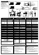
Application examples / Anwendungbeispiele / Exemples d'application
M
K1
K2
24VAC/DC, 110VAC, 230VAC
L1 L2 L3
AUXILIARY CIRCUIT
(ALARM OR INDICATION)
11
21
12
22
CADET 3
VERSION CCS2H
K1 (AUX)
K2 (AUX)
START
MOMENTARY
PUSH
BUTTON
STOP
MOMENTARY
PUSH
BUTTON
FUSES
CONTACT
PROTECTION
E.G. THERMAL
CUT OUT
A1 S13 S23 33X1 41 13 23
A2 S14 S24 34X2 42 14 24
MINOTAUR
MSR6R/T
SET TO D CHANNEL
SET TO R MODE
K1 K2
RESET
MOMENTARY
PUSH
BUTTON
GUARD
CLOSED
4
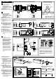
Optional GD2 accessory kit
2 x M5
Resistorx
security screws
2mm
GUARD STOP
Deutch /
Français
3
4
5
MIN.R 200mm
Minimum Operating Radius End-Entry using
flexible GD2 actuator
Minimum Operating Radius Front-Entry using
flexible GD2 actuator
MIN.R 60mm
MIN.R 150mm
MIN.R 60mm
IMPORTANT:-
Flexible actuator must
be used with GD2 end cap
GD2 kit comprises of stainless steel end cap, 2 x fixing screws and 1 flexible actuator
Anschlußdetails (abgebildet mit
geschlossener Schutztür und
eingesetztem Betätiger) /
CONNEXION –
Représentation détaillée (avec porte fermée
et émetteur inséré)
Hilfsstromkreis /
Circuit auxiliaire
Sicherheitsstromkreis /
Circuit de sécurité
Anschlußdetails (abgebildet mit
geschlossener Schutztür und
eingesetztem Betätiger) /
CONNEXION –
Représentation détaillée (avec porte fermée
et émetteur inséré)
Hilfsstromkreis /
Circuit auxiliaire
Sicherheitsstromkreis /
Circuit de sécurité
Start Druckknopftaster /
Bouton poussoir
de marche
Stop Druckknopftaster /
Bouton poussoir
d'arrêt
Schutzgitter geschlossen /
Porte fermée
Minotaur MSR6R/T eingestellt auf D
Kanal, eingestellt auf Betriebsart R
/
Minotaur MSR6R/T réglé sur le canal D
et réglé sur le mode R
Druckknopftaster für Neueinstellung /
Bouton poussoir de remise à zéro
Sicherungen /
Fusibles
Hilfskreis (Alarm oder Anzeige) /
Circuit
auxiliaire (alarme ou indication)
Kontaktschutz d.h. Wärmeausschaltung
/
Protection de contact e.g. coupe-circuit
thermique
Jedes Mal wenn die verriegelte
Schutzgittertür offen ist, prüfen, ob
Maschine isoliert und abgeschaltet ist.
WICHTIG: Nach Montage und
Inbetriebnahme sollten Betätiger,
Schalter u. Befestigungsschrauben für
Schalterdeckel zum Aufzeigen von
Eingriffen mit Lack oder ähnlichem
Material beschichtet werden /
Vérifiez que la machine soit arrêtée et
coupée lorsque la porte est ouverte.
IMPORTANT : Après l'installation et les
essais de mise en service, recouvrir de
vernis de blocage les vis de fixation de la
broche, de l’interrupteur et les vis du
couvercle
Optionaler GD2-Zubehörsatz /
Kit
d’accessoire GD2 en option
Der GD2-Satz enthält eine Endkappe aus
rostfreiem Stahl, 2
Befestigungsschrauben und 1 flexiblen
Betätiger. /
Le kit GD2 se compose d’un
chapeau d’extrémité en acier inoxydable,
de 2 vis de fixation et d’un émetteur
flexible.
Resistorx Sicherheitsschrauben /
Vis de
sécurité Resistorx
WICHTIG: Der flexible Betätiger muß
mit einer GD2-Endkappe verwendet
werden. /
IMPORTANT : l’émetteur flexible
doit être utilisé avec le chapeau d’extrémité
GD2
Schutztür-Arretierungen
/
Butée de porte
Mindestbetriebsradius-Vordereingang mit
flexiblem GD2-Betätiger
/
Rayon minimal
d’ouverture - entrée avant - avec émetteur
flexible GD2
Mindestbetriebsradius -
Endeingang mit
flexiblem GD2-Betätiger
/
Rayon
minimum de fonctionnement -
Entrée arrière-
avec émetteur flexible GD2
2221
3433
1211
2221
3433
1211
2221
3433
1211
2221
3433
1211
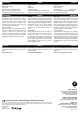
3
Connection details (shown with guard closed, actuator inserted)
31 32
33
34
2221
21
22
Aux. circuit
Safety circuit 2
Safety circuit 2
Safety circuit 3
Safety circuit 1
Safety circuit 1
1211
11
12
Brad Harrison connection
6 pole male, Type: BG 16885-008
Safety Circuit 2 (N/C)
Safety Circuit 1 (N/C)
1/2" UNF
15
6
2
22 21
4
3
12 11
Auxiliary Circuit (N/O) = 33/34
Safety Circuit 3 (N/C) = 31/32
31/3332/34