Guardmaster® 440G-LZ Guard Locking Switch User Manual
Important User Information Solid-state equipment has operational characteristics differing from those of electromechanical equipment. Safety Guidelines for the Application, Installation and Maintenance of Solid State Controls (publication SGI-IN001_-EN-P available from your local Rockwell Automation sales office or online at http://www.rockwellautomation.com/literature/) describes some important differences between solid-state equipment and hard-wired electromechanical devices.
Preface Read this preface to become familiar with the rest of the manual. It provides information concerning: • who should use this manual • the purpose of this manual • related documentation • conventions used in this manual Who Should Use This Manual Use this manual if you are responsible for designing, installing, programming, or troubleshooting systems that use the Guardmaster 440G-LZ guard locking switch.
Preface You can view and download publications at http:// www.rockwellautomation.com/literature/ . To order paper copies of technical documents, contact your local Rockwell Automation distributor or sales representative. Terminology 4 OSSD Output Signal Switching Device. Typically designates a pair of solid state signals pulled up to the DC source supply. The signals are usually tested for short circuits to the DC power supply, short circuits to the DC common, and short circuits between the two signals.
Table of Contents Important User Information . . . . . . . . . . . . . . . . . . . . . . . . . . . . . . . . . . . . 2 Preface Who Should Use This Manual . . . . . . . . . . . . . . . . . . . . . . . . . . . . . . . . . . . Purpose of This Manual . . . . . . . . . . . . . . . . . . . . . . . . . . . . . . . . . . . . . . . . Conventions Used in This Manual. . . . . . . . . . . . . . . . . . . . . . . . . . . . . . . Additional Resources. . . . . . . . . . . . . . . . . . . . . . . . . . . . . . . . . . . .
Table of Contents Appendix A Specifications Introduction . . . . . . . . . . . . . . . . . . . . . . . . . . . . . . . . . . . . . . . . . . . . . . . . . . Safety Ratings . . . . . . . . . . . . . . . . . . . . . . . . . . . . . . . . . . . . . . . . . . . . . . . . . Operating Characteristics. . . . . . . . . . . . . . . . . . . . . . . . . . . . . . . . . . . . . . Outputs. . . . . . . . . . . . . . . . . . . . . . . . . . . . . . . . . . . . . . . . . . . . . . . . . . . . . . .
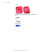
Chapter 1 General Description Guardmaster 440G-LZ Overview This Guardmaster 440G-LZ guard locking switch functions by extending a locking bolt from the switch through a hole in the actuator, thus preventing the opening of a guard. The locking bolt drive mechanism and logic ensure that the locking bolt is allowed to extend only when the corresponding actuator is detected within range. The appropriate actuator is detected by RFID coding.
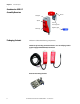
Chapter 1 General Description Guardmaster 440G-LZ Assembly Overview Actuator Locking bolt QR Code Actuator mounting bracket Switch body Packaging Contents Alignment guide The box includes the following components: Switch body including connection lead: 3 m or 10 m flying lead or pigtail equipped with M12 QD connector Actuator mounting bracket 8 Rockwell Automation Publication 440G-UM001A-EN-P — November 2013
General Description Chapter 1 Actuator Actuator-to-actuator mounting bracket mounting screws: 2 x T10 Torx Alignment guide Rockwell Automation Publication 440G-UM001A-EN-P — November 2013 9
Chapter 1 General Description Notes: 10 Rockwell Automation Publication 440G-UM001A-EN-P — November 2013
Chapter 2 Safety Concept Safety Standards Applied to the Guardmaster 440G-LZ Guard Locking Switch The Guardmaster 440G-LZ satisfies applicable requirements in the following standards related to functional and machinery assembly: • IEC 60947-5-1: 2003+A1: 2009 • IEC 60947-5-3: 1999/A: 2005 • IEC 61508:2010 SIL 3 • IEC 62061:2005 SIL 3 • EN/ISO 13849-1:2008/AC: 2009 Performance Level e (PLe), Category 4 • EN/ISO 14119:2013 • UL 508 17th Edition dated 3/19/2013 Introduction This section describes the saf
Chapter 2 The installed system, including the safety control system and the means by which the machine stops, must achieve the needed safety performance. The 440G-LZ is one element in the safety system.
Chapter 3 Installation and Wiring General Considerations The 440G-LZ guard locking switch is designed for use on guards that are engineered to be rigid without sag. A separately mounted latch (e.g. magnetic or mechanical) and mechanical stop are required. It can be used on Full Body Access guards that do not require escape release, emergency release or remote release guards, and in any situation where the alignment tolerance falls within the stated specification.
Chapter 3 Installation and Wiring 120 mm 120 mm If the recommended minimum proximity dimension is not observed, the units will fault. Orientation of Switches 14 Can be used in all mounting orientations.
Installation and Wiring Setting the Actuator Direction of Approach Chapter 3 The actuator can approach the switch from all four directions. Ensure the white arrow on the actuator aligns with the white arrow on the switch body. The actuator must be fitted to the actuator mounting bracket in such a manner that the white alignment triangles marked on both the actuator and switch body are in the installed position. Align the white triangles. 0.
Chapter 3 Installation and Wiring Ensure two fasteners are used with at least one fastener fitted close to the actuator bracket bend. Mounting the Assembled Actuator The following drawings show mounting possibilities when attaching to extruded aluminum profile and flat surface guard doors. Removal of the Actuator Plug This plug may be broken out from the actuator if a through hole is required to prevent a food trap when mounted on the hazard side of a guard door.
Installation and Wiring Mounting the Switch Body Chapter 3 Three M5 fasteners (not provided) are required for proper mounting to a rigid guard door frame. 3 x M5 Setting Actuator to Switch Alignment There are three ways to achieve proper alignment. 1. By setting gap “G” 2.5 mm (0.09 in.) [0…5 mm (0…0.19 in.)] 2. By mounting hole alignment ”H” 6.5 mm (0.25 in.) [4…9 mm (0.15…0.35 in.)] G H 3.
Chapter 3 Installation and Wiring ATTENTION: After installation, ensure that there is no possibility of lifting the actuator over the extended locking bolt. ATTENTION: After installation, ensure there is no possibility of collision when the actuator approaches the switch body. Actuator RFID Setting Switches with standard coded actuators These switches are ready for use and need no special RFID setting.
Installation and Wiring Chapter 3 Learning Sequence as Indicated by the Status/Diagnostic LEDs Actuator present Blinking green, 1 Hz rate Verifying actuator Blinking green/red, 1 Hz rate (15 sec) Programming switch (15 sec) Blinking green/red, 4 Hz rate (15 sec) Program finalization Blinking green (remaining number of times a new actuator may be acquired, 15 sec) Ready state (learning process is complete) Solid green (Power-to-release) Solid red (Power-to-lock) Learning Additional “Multi-Time” A
Chapter 3 Installation and Wiring Status/Diagnostic LED Error Codes During the Learning Process Proving Basic Lock Function The following code sequences persist until a Power On/Off cycle is completed.
Installation and Wiring Chapter 3 Wiring 3 Lock Command 8 Safety A+ 2 24V DC+ Keyway 1 Aux 7 0V 4 Safety B+ 5 Safety A 8-Pin Micro (M12) Color White Brown 8-Pin Cordset Green 889D-F8AB-* or Yellow cable version Grey Pink Blue Red Connections Systems 6 Safety B Function Aux 24V DC+ Lock Safety B+ Safety A Safety B Gnd/0V Safety A+ Pin 1 2 3 4 5 6 7 8 The following connection system components facilitate connection: Safety-wired Splitter/T-Port Cat.
Chapter 3 Installation and Wiring Safety-wired Shorting Plug Cat. No 898D-418U-DM 2 5 1 3 4 Pin 1 Pin 2 Pin 3 Pin 4 Pin 5 PWR OSSD 1+ NA OSSD 2+ NA 8-pin Device Patchcords Cat. No. 1 meter, 8-pin 889D-F8ABDM-1 2 meters, 8-pin 889D-F8ABDM-2 5 meters, 8-pin 889D-F8ABDM-5 10 meters, 8-pin 889D-F8ABDM-10 Note: Add the letter “S” to above cat. nos. for stainless steel connectors; e.g. 889DS-F8ABDM-1 5-pin Patchcords Cat. No.
Chapter 4 Description of Operation Status/Diagnostic LEDs During Operation During operation, the LEDs indicate the status of the Guardmaster 440G-LZ guard locking switch as follows: Power-to-Lock Versions Guard Status Lock CMD OSSD Input Lock Status Power on and lock Open or CMD off closed Off Off or on Unlocked Blinks 6x green then solid red Off Lock CMD on, door Open open On Off or on Unlocked Fast flash green Off Lock CMD on, door Closed closed On Off Locked Slow flash green Off L
Chapter 4 Description of Operation Status/Diagnostic LEDs During Troubleshooting This section explains the meaning of the various LEDs during troubleshooting. LED Status Switch Status Off Not powered Solid green Door shut, locked, and OSSDs are ON. Fast flash, green (4 Hz) Waiting to lock, actuator is not within range Slow flash, green (1 Hz) Door shut, locked. OSSDs are OFF because there’s no safety input signal. Solid red (PTL versions) Door open or shut, not locked. No lock signal.
Description of Operation Chapter 4 Guardmaster 440G-LZ Wiring with GSR Relay 440G-LZS 889D-F8AX-X Brn Yel Red 24V DC Supply Reset Wht Pnk Gry Blu N/C Pigtail Grn E-Stop Power In1 In2 Out Logic A2 A1 + 24VDC DI S11 L11 S12 S22 S32 S42 IN2 IN1 0 LOGIC 8 L12 S21 Test Out 7 Y32 6 5 1 2 3 4 S34 A1 A2 + 24VDC B1 B2 37 38 47 48 37 38 47 48 EMD 17 18 27 28 13 14 23 24 L12 L11 X32 17 18 27 K1 28 K2 K1 K2 M 24V DC COM Rockwell Automation Publication 440G-UM001A-
Chapter 4 Description of Operation Point to Point I/O with Unlock request.
Description of Operation Chapter 4 Troubleshooting Series Circuit +24 24V DC Power RTN Supply Switch 1 Switch 2 Switch 3 Switch 4 Switch 5 1606XL120D Gre Bro wn en Gre Actuator 2 is in sensing range and guard is locked. Guard 2 functions properly. OSSDs are energized to 24V. Green LED is ON. Gre 0V 0V Lock/Unlock Actuator 3 is in sensing range and guard is locked. Guard 3 has a fault. See Diagnostic table. Red LED is flashing.
Chapter 4 Description of Operation OSSD Output Test Pulses The Guardmaster 440G-LZ guard locking switch uses test pulses to check for OSSD output faults. This process is illustrated graphically as follows: Occurs every 25 ms Occurs every 11 sec Safety A ˂ 600 μs 300 μs Occurs every 25 ms Safety B Occurs every 11 sec ˂ 600 μs 300 μs Auxiliary/Manual Release The manual release is provided to allow you to unlock the guard door in the event of unforeseen and uncommon circumstances. < 2.5 (0.
Appendix A Specifications Introduction This appendix provides the specifications for the Guardmaster 440G-LZ guard locking switch. Note: The holding force Fzh is in accordance to EN/ISO 14119:2013, clause 5.7.4. Additional validation was performed in accordance with IEC 60947-5-1:2009, clause C.1.2.2.
Appendix A Specifications Peak current, during turn-on or after Lock/ Unlock operation 400 mA Duration of peak current, at turn-on or after Lock/Unlock operation 100 ms Maximum number of switches connectable in series Unlimited, See Chapter 4, Unit Response Times Operating voltage Ue 24V DC + 10% / -15% Class 2 SELV Maximum frequency of operating cycles 0.2 Hz Dwell time between subsequent locking/ unlocking 2.
Specifications Environmental General Protection Certifications Appendix A Operating temperature [C (F)] 0…55º (+14…131º) Storage temperature [(C (F)] -25…75º (+13…167º) Operating humidity 5…95%, relative Enclosure ingress rating NEMA 3, 4x, 12, 13, IP66, IP67, IP69K Shock and vibration IEC 68-2-27 30 g, 11 ms/IEC 68-2-6 10…55 Hz Hygienic ISO 14159:2004 and EN 1672-2005 (for part of the machine defined as “food splash area”) Washdown Suitable for sodium hydroxide-based washdown fluids Rad
Appendix A Specifications Compliance to European Union Directives This product bears the CE Mark and is approved for installations within the European Union and EEA regions. It has been designed and tested to meet the following directives (Machine Safety and EMC). For a complete list of standards used (including Machine Safety Directive and EMC Directive), see EU Declaration of Conformity on page 37 of this manual. Overall Dimensions Switch Body 9.525 (0.37) dia. 9.5 (0.37) 33 (1.29) 22.5 (0.
Specifications Appendix A Switch Mounting Bracket 440G-LZAM2 +1 R6 -3 40 (1.57) 54 (2.12) 2x 15 (2x 0.59) 100 (3.93) 2x 6.35 (2x 0.25) 145.5 (5.72) 2x 33 (2x 1.3) 6.35 (0.25) 4x R6 ± 1 mm 3x 5.5 (3x 0.22) 22.75 (0.89) 18.5 (0.73) 2x 15.5 (2x 0.61) 3 x 5.5 (3x 0.22) Rockwell Automation Publication 440G-UM001A-EN-P — November 2013 2x 31.5 (2x 1.24) 6x M5 x 0.
Appendix A Cat. Nos. Specifications Complete switches, including switch body, actuator and actuator mounting bracket Cat. No. Connection Type Power-toRelease Power-to-Lock Actuator Coding 3 m lead 10 m lead 6 in.
Appendix B Typical Installations Switch Mounted Parallel to Hinge Axis The X and Y positions can be adjusted using the slotted holes of the mounting bracket and appropriate selection of the three Y pairs of actuator bracket holes, once the bracket is centered. Mounting The tolerance to misalignment is bracket ±2.5 mm. Z X 440G-LZAM2 The Z (height) position is adjusted by sliding the actuator bracket up/ down on the profile.
Appendix B Typical Installations Switch Mounted Perpendicularly to Hinge Axis The Z (height) position is adjusted by sliding the actuator bracket up/ down on the profile. If the setting gap is centered between the minimum of 0 mm and the maximum of 5 mm, a tolerance to misalignment of ±2.5 mm is achieved. Y Z X The X and Y positions can be adjusted using spacers underneath the switch and appropriate selection of the three pairs of actuator bracket holes, once the bracket is centered.
Typical Installations Appendix B EU Declaration of Conformity Identification of the product: Guard Locking Safety Switch Name and address of the manufacturer: Rockwell Automation, Inc. 2 Executive Drive Chelmsford, MA 01824 USA Name and address of the authorised representative: Rockwell Automation B.V. Rivium Promenade 160 2909 LM Capelle aan den Ijssel The Netherlands This declaration of conformity is issued under the sole responsibility of the manufacturer.
Appendix B Typical Installations Series 1 Catalogue number Description 440G-LZ21**** Guard locking RFID non-contact safety switches Accessories 889D-F8AB-* Cordset for use with sensors with Micro (M12) connector Patchcord for use with sensors with Micro (M12) connector 889D-F8ABDM-* 1) If no series number is given, then all series are covered 2) Yes = Product is certified to this directive.
Rockwell Automation Support Rockwell Automation provides technical information on the web to assist you in using its products. At http://www.rockwellautomation.com/support, you can find technical manuals, technical and application notes, sample code and links to software service packs, and a MySupport feature that you can customize to make the best use of these tools. You can also visit our Knowledgebase at http://www.rockwellautomation.