
Safety Relay User Manual Owner's manual


Rockwell Automation Publication 440C-UM001C-EN-P - November 2014 95
Chapter 14
Modbus Communication
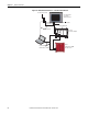
The CR30 uses Modbus RTU communications to transfer status information
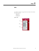
and control signals to Micro800® controllers and human-machine interfaces like
the Allen-Bradley PanelView.
The Modbus configuration of the CR30 is fixed to Modbus RTU slave at
address1.
For more information on PanelView, refer to the following documents:
• User Manual: 2711C-UM001_-EN-P
• Quick Start Guide: 440C-QS001_-EN-P
Modbus Mapping
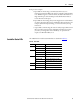
The CR30 Modbus addresses are mapped to parameters shown in Ta b le 1 6. The
addresses in the range of 1…512 can be accessed as coils. The fault log can be
accessed by holding register reads; each address contains 16 bits of data.
Table 16 - Modbus Addresses
Modbus Address Parameter
000001…000016 Modbus serial input data
000025…000028 Input Data for Plug-in 1 Terminals I-00…I-03
000033…000036 Output Data for Plug-in 1 Terminals O-00…O-03
000265 Processor HW fault
000266 Safety Input HW fault
000267 Safety Output HW fault
000268 Power supply fault / Main transistor fault
000269 Communication fault
000270 Configuration fault (wrong revision, invalid configuration)
000271 Time out (Clock monitoring)
000272 Plug-in fault
000273…000294 State of Embedded Terminals 00…21
000297…000300 Input of Plug-in 2 Terminals I-00…I-03
000301…000304 Output of Plug-in 2 Terminals O-00…O-03
000305…000328 State of Safety Monitoring Function (SMF) 0…23
000329…000344 State of Logic Level A Instance (LLA) 0…15
(1)
000345…000360 State of Logic Level B Instance (LLB) 0…15
000361…000376 State of Safety Output Function (SOF) 0…15