
Safety Relay User Manual Owner's manual

64 Rockwell Automation Publication 440C-UM001C-EN-P - November 2014
Chapter 9 Safety Monitoring Functions
Single Wire Safety Input
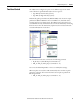
When configured for this type of input, the CR30 expects a Single Wire Safety
(SWS) input signal from a GSR relay or a safeguarding device that has an SWS
output signal. The GSR relay family includes the CI, SI, DI, DIS, GLP, GLT,
EM, and EMD modules. Each of these modules provides the SWS signal on
terminal L11.
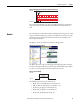
Figure 65 - Single Wire Safety Function Block
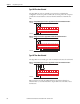
Only terminals 10 and 11 of the CR30 can be configured to receive the SWS
signal.
• EI_10…EI_11 (embedded input terminals 10…11)
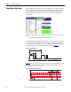
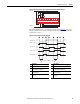
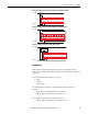
The SWS signal is a long pulse followed by a short pulse, which is repeated while
the signal is active. The SWS is active when the safety outputs of a GSR safety
relay are ON. When the SWS is inactive, the SWS signal is 0V. The timing and
voltage characteristics of the SWS waveform are shown in Figure 66
.
Figure 66 - SWS Waveform
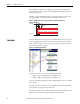
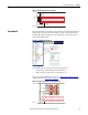
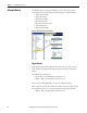
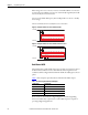
Figure 67 shows an example schematic of the connection of the SWS from other
modules in the GSR family of relays. The CR30 and GSR modules must be
connected to the same 24V Common.
Figure 67 - SWS Connection Schematic
1ms
0 V
+24 V
4ms
0.7ms
0.5ms
Active (ON) Inactive (OFF)
+24V DC
24V Com
GSR Module
L11A1
A2
GSR Module
L11A1
A2
05
CR30
020100 03 04
A1 15 20 2116
06
18A2
07
19
08 10 11
12 13 14
09
17