
Safety Relay User Manual Owner's manual


50 Rockwell Automation Publication 440C-UM001C-EN-P - November 2014
Chapter 9 Safety Monitoring Functions
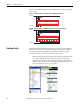
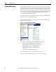
You can modify the number and types of inputs:
• 2 N.C.
• 2 OSSD
• 1 N.C.
Pulse testing can be disabled or set to 2 Sources. When 2 Sources is selected, the
next available test sources are automatically selected. You can modify the sources
afterward.
You can use the default Discrepancy Time and Input Filter or choose to modify
these settings.
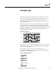
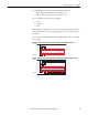
Figure 40 - Example Schematic of a Dual Channel Safety Gate Switch Without Test Pulses
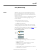
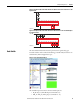
Figure 41 - Example Schematic of a Dual Channel Safety Gate Switch Using Test Pulses A and B
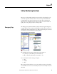
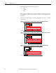
Figure 42 - Example Schematic of a Dual Channel Safety Gate Switch Using OSSD Outputs
+24V DC
24V Com
05
CR30
020100 03 04
A1 15 20 2116
06
18A2
07
19
08 10 11
12 13 14
09
17
+24V DC
24V Com
AB
05
CR30
020100 03 04
A1 15 20 2116
06
18A2
07
19
08 10 11
12 13 14
09
17
+24V DC
24V Com
A1
A2
05
CR30
020100 03 04
A1 15 20 2116
06
18A2
07
19
08 10 11
12 13 14
09
17