
Safety Relay User Manual Owner's manual


Rockwell Automation Publication 440C-UM001C-EN-P - November 2014 49
Safety Monitoring Functions Chapter 9
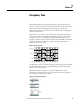
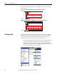
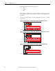
Figure 37 - Example Feedback Schematic with Two Feedback Contacts Connected in Series to One
Input Terminal
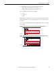
Figure 38 - Example Feedback Schematic with Four Feedback Contacts Connected Individually to
Four Input Terminals
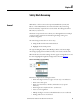
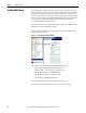
Gate Switch
The Gate Switch function block sets the parameters for typical safety gate
interlock switches. In the CCW, click and drag (or double-click) the block to an
available Safety Monitoring Function spot.
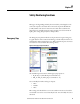
Figure 39 - Gate Switch Function Block
The available input selections for the Gate Switch inputs are:
• EI_00…EI_11 (embedded input terminals 00…11)
• MP_12…MP_17 (multi-purpose terminals 12…17)
K1
K2
+24V DC
24V Com
05
CR30
020100 03 04
A1 15 20 2116
06
18A2
07
19
08 10 11
12 13 14
09
17
K1 K2
+24V DC
24V Com
05
CR30
020100 03 04
A1 15 20 2116
06
18A2
07
19
08 10 11
12 13 14
09
17
K1 K4K3K2
K1 K2 K3 K4