
Safety Relay User Manual Owner's manual


46 Rockwell Automation Publication 440C-UM001C-EN-P - November 2014
Chapter 9 Safety Monitoring Functions
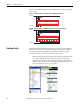
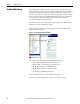
You can use the default Discrepancy Time and Input Filter or choose to modify
these settings.
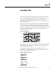
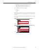
Figure 31 - Example Schematic of a Dual Channel E-stop Without Test Pulses
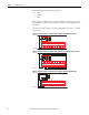
Figure 32 - Example Schematic of a Dual Channel E-stop Using Test Pulses A and B
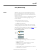
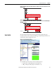
Enabling Switch
The Enabling Switch function block sets the parameters for typical enabling (or
hold-to-run) devices. In the CCW, click and drag (or double-click) the block to
an available Safety Monitoring Function spot. When mechanical operated
contacts are used, these contacts must be direct-acting contacts.
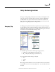
Note: This function block is intended to be used only in applications with
a 3position enabling switch that only allows activation of its outputs
(closed contacts) when the operator presses and holds the switch into its
middle position. The switch has to be designed using a mechanical force to
reset to its default off (contact open) position.
Figure 33 - Enabling Switch Function Block
+24V DC
24V Com
05
CR30
020100 03 04
A1 15 20 2116
06
18A2
07
19
08 10 11
12 13 14
09
17
+24V DC
24V Com
AB
05
CR30
020100 03 04
A1 15 20 2116
06
18A2
07
19
08 10 11
12 13 14
09
17