
Safety Relay User Manual Owner's manual

Rockwell Automation Publication 440C-UM001C-EN-P - November 2014 133
Specifications Appendix A
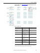
Reaction Time
The reaction time is the time to enable the safety output function when
activating the safety input devices and performing a valid reset operation. The
overall reaction time of the safety function considers the whole safety chain,
including the safety input device, logic device, and actuator. The reaction time
must be calculated for each safety function.
Tab l e 29
shows the possible chain with all considerable reaction times for a safety
function.
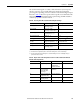
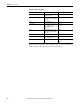
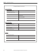
Table 29 - Safety Function Reaction Times
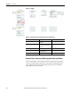
Figure 134 - Example 1:
Description Where to find: Value
Feedback Feedback Input Filter time From SMF configuration
“advanced settings”
(3)
(3) The maximum input filter time must not be greater than 250 ms.
Safety Sensors Reaction time of sensor
device
Sensor operating manual
SMF Configured Input Filter
time
From SMF configuration
“advanced settings”
(3)
Reset/Restart Reset/Restart Pulse Time +
2 x Filter Time
(1)
(1) If input filter time settings are not disabled, the recommended setting is “0”. Values greater “0” must be considered for the
reaction time.
Reset Pulse: max 3s
Input Filter Time from SMF
configuration
3s + 2 x Input Filter
Logic Internal execution time to
process input signal,
routing, and output
processing
(2)
(2) The internal execution time is static and independent of the number of function blocks that are configured for the safety function.
From technical
specification
100 ms
SOF Configured On-Delay time From SOF configuration
Actuator Safety switching device
controlling the load
Actuator Operating manual
To ta l