
Safety Relay User Manual Owner's manual


12 Rockwell Automation Publication 440C-UM001C-EN-P - November 2014
Chapter 1 Overview
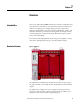
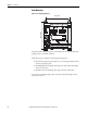
CR30 Hardware Details
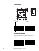
Figure 2 - Hardware Details
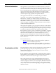
Max Number of Inputs and Outputs
Many of the inputs and outputs can be configured for different roles. The
following table shows the maximum number of terminals for a specific function.
Assigning a configurable terminal to one role reduces the risks of its use as
another role and reduce the allowed maximum number of terminals for other
functions.
Description Description
1 Status indicators 10 Verification button
2 Plug-in latch 11 Din Rail mounting latch
3 Plug-in screw hole 12 Input status
4 40-pin high-speed plug-in connector 13 Power status
5 I/O and Power terminal blocks 14 Run status
6 Mounting screw hole/mounting foot 15 Fault status
7 Right-side cover 16 Lock status
8 RS-232 non-isolated serial port 17 Serial communications status
9 Type B connector USB 18 Output status
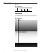
Function Max Allowed Function Max Allowed
Safety inputs, normally closed up to 18 Pulse test outputs up to 6
Safety inputs, normally open up to 6 OSSD safety outputs up to 10
Single-wire safety input up to 2 Non-pulsed (standard) outputs up to 6
Single-wire safety output up to 2
11
12
13
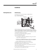
Status Indicators
14
15
16
17
18
1
10
234 5
5
6
698
7