
Safety Relay User Manual Owner's manual


100 Rockwell Automation Publication 440C-UM001C-EN-P - November 2014
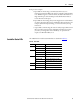
Chapter 14 Modbus Communication
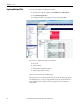
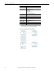
• LocalAddr - The results are placed in LocalAddr. There is no need to
make changes.
Figure 118 - Read Local Variables
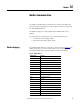
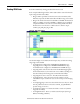
Sending Reset to CR30
The Reset function must use a separate Modbus message block. Another
constraint that must be considered is reset signal must be between 0.5…3 s long.
In the example below, a momentary button is connected to embedded terminal
_IO_EM_DI_02.
• Rung 3: The push button initiates a TONOFF timer. The timer is set for a
100ms delay ON and a 1100 ms delay OFF. This provides a reset signal of
1 s.
• Rung 4: The Modbus message is sent with every scan of the ladder. The
reset is executed because the reset value goes from 0 to 1 and back to 0
within the acceptable range of 0.5…3 s.
• Rung 5: When the TONOFF block goes LO, embedded output
_IO_EM_DO_01 goes LO and moves the value of 0 into Reset Addr.
• Rung 6: When the TONOFF block goes HI, embedded output
_IO_EM_DO_01 goes HI and moves the value of 1 into Reset Addr.
Figure 119 - Reset Ladder Diagram