Guardmaster® 440C-CR30 Software Configurable Safety Relay Quick Start Guide
Important User Information Solid-state equipment has operational characteristics differing from those of electromechanical equipment. Safety Guidelines for the Application, Installation and Maintenance of Solid State Controls (publication SGI-IN001_-EN-P available from your local Rockwell Automation sales office or online at http://www.rockwellautomation.com/literature/) describes some important differences between solid-state equipment and hard-wired electromechanical devices.
Quick Start Guide Table of Contents Introduction . . . . . . . . . . . . . . . . . . . . . . . . . . . . . . . . . . . . . . . . . . . . . . . . . . . . . . . . . . 1 Assumption . . . . . . . . . . . . . . . . . . . . . . . . . . . . . . . . . . . . . . . . . . . . . . . . . . . . . . . . . . 1 Schematic/Setup . . . . . . . . . . . . . . . . . . . . . . . . . . . . . . . . . . . . . . . . . . . . . . . . . . . . . 1 Configuring the Guardmaster 440C-CR30 . . . . . . . . . . . . . . . . . . . . . . . . . . .
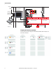
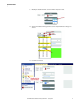
Quick Start Guide +24V DC To Ethernet Network PanelView C600 2711C-T6T Modbus Master K1 Stratix 2000 1783-US05T Unmanaged Ethernet Switch Trojan T15 GD2 440K-T11463 K2 00 01 02 03 04 05 06 07 08 09 10 11 1 3 6 I-00 I-01 COM +24 O-00 O-01 2 5 4 7 8 1761-CBL-PM02 2080-IQ4OB4 440C-CR30-22BBB USB Cable Male A to Male B Personal Computer A B A1 A2 12 13 14 15 16 17 18 19 20 21 I-02 I-03 COM -24 O-02 O-03 700HPS-XZ24 Relay K1 K2 700HN-123 Base 24V Com Configuring the Guardmaster 440C-CR30 In
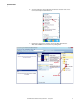
Quick Start Guide 1. Start the CCW. Click on the Windows Start button and then click on the Connected Components Workbench. 2. Expand the catalog items. Double click on the 440C-Guardmaster 440C-CR30-22BBB to load it into the Project Organizer.
Quick Start Guide 4 3. Double click on the controller. 4.
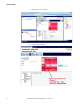
Quick Start Guide 5. Open the Logic Editor. Also note that the Digital Input Module shows in the project. 6. Load the e-stop.
Quick Start Guide 6 7. Load the Gate Switch. 8. Load the Feedback monitoring. (Use the vertical scroll bar to adjust the workspace up to see the next available safety monitoring spot.
Quick Start Guide 9. Modify the feedback block. Set the number of inputs to two. 10. Assign the feedback wiring terminal. Set the Input Terminals to Plug-in 00 and 01. 11. Load the reset block.
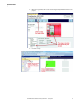
Quick Start Guide 12. Change the reset input terminal to Modbus 00. 13. Load the Immediate OFF block. 14. Change the Feedback connection to SMF3 (Safety Monitoring Function 3). 15. Change the reset Input to SMF4 (Safety Monitoring Input 4).
Quick Start Guide 16. Load an AND block. 17. Make the connections.
Quick Start Guide 18. The final diagram should look like this. The CCW automatically created a ‘Pass Through’ block in Logic Level B.
Quick Start Guide 19. Configure the LEDs.
Quick Start Guide 20. Save the Project.
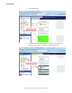
Quick Start Guide 21. Observe the Serial Port Settings.
Quick Start Guide We will be using these Modbus Addresses. 22. Download the project.
Quick Start Guide 23. Click No to maintain project in Program mode. 24. Verify the Project. • If this step is not completed, the CR30 will stop functioning after 24 hours. The user can cycle the power to the CR30 and it will function again for another 24 hours. • If this step is completed, the CR30 will continue to function after 24 hours and will run indefinitely. • Verification can only take place while the CCW is connected to the CR30, and the CR30 is in program mode.
Quick Start Guide 25. The CCW generates the Safety Verification ID. Press OK to continue. 26. Confirm that the Verification ID is present in the CCW Project tab workspace and the CR30 is returned to the Run mode. Note that the Verification ID is not saved with the CCW project file. It is saved in the CR30, so that when power is cycled, the user can upload the project from the CR30 and view the verification ID and the CR30 functions beyond the 24 hour limit.
Quick Start Guide 1. Click the Create and Edit button. 2. Set up Communications.
Quick Start Guide 3. We will use the multi-state indicator to indicate the status of the Guardmaster 440C-CR30 inputs, outputs and fault status. We will use a multi-state pushbutton for the reset function. To do this, we need to create tags, then place icons onto the screen and link the icons to the tags. This guide will show how to set up one indicator and the reset button. The user can follow these same steps to create additional indicators. Create a tag for Safety Monitoring Function 1.
Quick Start Guide 5. Put the SMF1 Indicator on the screen. 6.
Quick Start Guide 20 7. The multi-state indicator has a default setting of four states plus an error state. 8. We only want to use two states, plus the error state. Delete states three and four. 9. Change the colors for the states.
Quick Start Guide 10. Modify the text. This first multi-state indicator will show the status of the e-stop function block. When the multi-state value is zero, we want the text to show OFF and the background color to be orange. When the value is one, we want to text to show ON and the color to be green. If an error occurs we want the color to show red and to display ERR. 11. Make the e-stop connection. 12. Add the reset button.
Quick Start Guide 13. Set up the color, text and default states for the reset button. 14. Stretch the reset icon and make the Write Tag connection to the reset. 15. Add a Goto Config button.
Quick Start Guide 16. Validate the screen and application 17. Save the file. 18. Go to the home page. 19. Run the application.
Quick Start Guide Verify Operation 1. Open the Logic editor in the CCW.
Quick Start Guide 2. Confirm the LEDs are ON. The run LED is flashing. 3. Press and release the reset button on the PanelView C600 within 0.
Quick Start Guide 4. Confirm the LEDs. 5. Press the e-stop button. The e-stop on the PanelView turns orange and shows OFF.
Quick Start Guide The Logic diagram shows the e-stop, AND and immediate OFF block are grey, and the feedback block is green.
Quick Start Guide Fault and Status Reporting In this section, we will configure the PanelView C600 to display the status and faults in the safety system. 1. The Modbus Mapping addresses for Status and faults is shown below. 2. 28 Add the following tags to the PanelView C600.
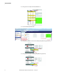
Quick Start Guide 3. Add the multi-state indicators for the faults. 4. Press the reset button to get the outputs on. Create a short-circuit from terminal 0 to terminal 1. 5. The PanelView C600 will look like this. Crossfault 12 – a crossfault occurred on terminal 12, which is Input Test Pulse A. E-STOP OFF – since Input Test Pulse A is used by the e-stop SMF, it turns OFF. Gate OFF – since Input Test Pulse A is also used by the Gate SMF, it turns OFF. The fault causes the Output to turn OFF.
Quick Start Guide 30 Rockwell Automation Publication 440C-QS001A-EN-P — January 2014
Rockwell Automation Support Rockwell Automation provides technical information on the web to assist you in using its products. At http://www.rockwellautomation.com/support, you can find technical manuals, technical and application notes, sample code and links to software service packs, and a MySupport feature that you can customize to make the best use of these tools. You can also visit our Knowledgebase at http://www.rockwellautomation.