
Instruction Manual

ColorSight Series 9000 PHOTOSWITCH
R
Photoelectric Sensor 9
75027--031--01(A), November 1999
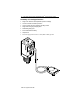
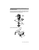
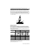
Aligning the Fiber Optic Cable Head (A--B #60--2694)
The head assembly should be positioned and securely fastened so that
the lens is 27mm (1 1/16in) from the target to be sensed. When operating
the sensor in COLOR ONLY mode this tolerance should not exceed
+/-- 3mm (1/8in). For high precision c olor discrimination applications using
the COLOR PLUS INTENSITY mode, the tolerance can be no more than
+/-- 0.75mm (1/32in).
Target
Distance
plus tolerance
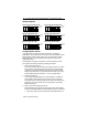
Wiring the Sensor
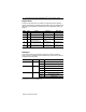
Models of ColorSight are available in one of three different connection
types as identified in the following table. Allen-Bradley recommends the
use of the 889 Series of cordsets and patchcords on the quick-disconnect
models. All external wiring should conform to the National Electric Code
and all applicable local codes.
Designation
Lead Color Pin Assignment
2m Cable 5-pin Micro QD 5-pin Mini QD
1
3
2
4
5
1
3
2
4
5
V+ or V-- Brown 1 4
V-- or V+ Blue 3 2
Signal output Black 4 1
Fault output Orange 5 3
Learn/Gate input White 2 5
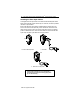
Polarity of supply voltage defines sensor output type –i.e. PNP or NPN
PNP when brown lead connected to V+ and blue lead connected to V--
NPN when brown lead connected to V-- and blue lead connected to V+
Function determined by selector switch S6