
Instruction Manual
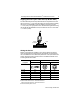

6 ColorSight Series 9000 PHOTOSWITCH
R
Photoelectric Sensor
75027--031--01(A), November 1999
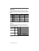
Dip-Switches
A bank of 6 dip-switches are provided for configuring various operating
modes and parameters available with ColorSight. These are defined in the
table below and explained in further detail in the Configuration section on
page 10.
Switch Label Function Switch Up Switch Down
S1 None Not used — —
S2 /= Select target match/no match Output inactive Output active
S3 TD/0 Enable/disable time delay 50ms time delay active No time delay
S4 CI/C Select color + intensity
mode/color only mode
Color + intensity mode
active
Color only mode active
S5 SG/AV Select single/average mode Single sample mode
active
Average sample mode
active
S6 GT/LRN Select gate/remote learn mode Input functions as gating
input
Input functions as remote
learn
Factory default
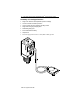
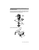
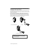
Indicators
Three LED indicators are provided to indicate a variety of conditions
making it easy for installation and troubleshooting. The function of each is
described in the table below.
Label Color State Condition
PWR Green OFF Sensor power not present
Steady Sensor power present
OUTPUT/LEARN Yellow OFF Output inactive
Steady Output active
Flash Learn mode activated
FAULT/SCP Red OFF Sensor operating normally
Steady Marginal detection of target
Flash Output SCP active
LED also OFF when LEARN pushbutton depressed.
Includes failure to learn color during LEARN process.