PHOTOSWITCHR Photoelectric Sensors ColorSight Series 9000 User Manual Introduction This manual explains how to install, adjust, and program ColorSight Series 9000 photoelectric sensors
ColorSight Series 9000 PHOTOSWITCHR Photoelectric Sensor Table of Contents General Specifications . . . . . . . . . . . . . . . . . . . . . . . . . . . . . . . . . . 3 Summary of ColorSight Features . . . . . . . . . . . . . . . . . . . . . . . . . . 4 User Interface . . . . . . . . . . . . . . . . . . . . . . . . . . . . . . . . . . . . . . . . 5 Pushbutton . . . . . . . . . . . . . . . . . . . . . . . . . . . . . . . . . . . . . . . . . . 5 8 Turn Knob . . . . . . . . . . . . . . . . . . . . . . . . .
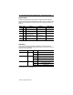
ColorSight Series 9000 PHOTOSWITCHR Photoelectric Sensor 3 Environmental Mechanical Electrical Optical Cat No.
ColorSight Series 9000 PHOTOSWITCHR Photoelectric Sensor Summary of ColorSight Features Single color detection with adjustable precision settings Local and remote self teach operation Color only and color plus intensity operating modes Single and averaging sampling rates Selectable gating input Fixed selectable OFF delay Output SCP Reversible supply leads for Source or Sink (PNP or NPN) operation 75027-- 031-- 01(A), November 1999
ColorSight Series 9000 PHOTOSWITCHR Photoelectric Sensor 5 User Interface Using an instrument screwdriver, open the top cover of the sensor to gain access to the user interface panel. This panel contains a pushbutton, 8-turn knob, 6 dip-switches, and LED indicators for configuring and viewing the sensor’s operation and status. A more complete description of each item is described below.
ColorSight Series 9000 PHOTOSWITCHR Photoelectric Sensor Dip-Switches A bank of 6 dip-switches are provided for configuring various operating modes and parameters available with ColorSight. These are defined in the table below and explained in further detail in the Configuration section on page 10.
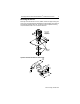
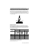
ColorSight Series 9000 PHOTOSWITCHR Photoelectric Sensor 7 Mounting the Sensor Securely mount the sensor on a firm, stable, surface or support using one of the many mounting brackets available from Allen-Bradley. The sensor is supplied with hardware kit #129--130 which contains a plastic mounting nut, lock washer, 2 M5 x 0.8 x 53 screws and nuts. M5 x 0.8 x 53 Combination Screws and Nuts (Supplied) Hardware Kit (Supplied) Optional Swivel/Tilt Bracket A--B #60--2439 1.100 (27.94) 1.150 (29.21) 1.
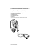
ColorSight Series 9000 PHOTOSWITCHR Photoelectric Sensor Installing the Fiber Optic Cables ColorSight has been optimized to work with the Allen-Bradley #60--2694 Fiber Optic Assembly. Other cables may be used also, but with a possible reduction in performance. Ensure that the fiber optic cable is installed with the emitter end in the source side of the sensor (left entry when viewed from the sensor front face) and the receiver end in the receive side of the sensor.
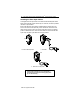
ColorSight Series 9000 PHOTOSWITCHR Photoelectric Sensor 9 Aligning the Fiber Optic Cable Head (A--B #60--2694) The head assembly should be positioned and securely fastened so that the lens is 27mm (1 1/16in) from the target to be sensed. When operating the sensor in COLOR ONLY mode this tolerance should not exceed +/-- 3mm (1/8in). For high precision color discrimination applications using the COLOR PLUS INTENSITY mode, the tolerance can be no more than +/-- 0.75mm (1/32in).
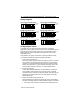
ColorSight Series 9000 PHOTOSWITCHR Photoelectric Sensor Wiring Diagrams Cable version wired with PNP outputs Brown White Orange Black Blue Diagnostic Load Sensor Load White Orange Black Blue -- Diagnostic Load Sensor Load 1 2 5 4 3 Teach/Gate -- 4 Diagnostic Load Sensor Load + -- 10--30V DC Diagnostic Load Sensor Load Teach/Gate + Mini QD wired with NPN outputs + 10--30V DC Diagnostic Load Sensor Load -- 10--30V DC Teach/Gate Micro QD wired with NPN outputs + 10--30V DC Mini QD wired
ColorSight Series 9000 PHOTOSWITCHR Photoelectric Sensor 11 2. Color Plus Intensity which measures the absolute RGB values. The selection of one of these modes is made by toggling dip switch S4. For most applications, the Color Only mode will be suitable. When minute changes in target color must be recognized the Color Plus Intensity mode should be used. 4. Set the sampling rate, S5 ColorSight can be configured to operate at one of two fixed sampling rates.
ColorSight Series 9000 PHOTOSWITCHR Photoelectric Sensor 12. Sequence the target in and out of the sensors field of view to ensure proper color discrimination. It may be necessary to adjust the 8-turn knob to a higher setting to provide a higher degree of color discrimination. 13. Congratulations! The sensor has successfully learned the target. Dimensions—inches (mm) 2.190 (55.62) 40 (1.58) 74.93 (2.950) Ref M30 X 1.5 External Thread 1/2 NPSM Internal Thread 24.64 (0.970) 30.35 (1.195) 41.91 (1.
ColorSight Series 9000 PHOTOSWITCHR Photoelectric Sensor 13 Accessories Description Catalog Number 1.8m (6ft) mini QD Cordset 889N- F5AF- 6F 2m (6.
ColorSight Series 9000 PHOTOSWITCHR Photoelectric Sensor Terms and Definitions Average Mode A mode of operation, which takes multiple samples of the target being sensed. A typical application using this mode would be the color discrimination of textured materials such as textiles and lumber. Color Only Mode A mode of operation found in some color recognition sensors in which the target color is determined by measuring the hue and chroma attributes only.
ColorSight Series 9000 PHOTOSWITCHR Photoelectric Sensor 15 Troubleshooting Green LED does not illuminate Ensure power is connected to the sensor. Target cannot be learned Ensure fiber optic cables are securely seated in sensor cavity. Ensure emitter (blue) side of fiber optic cable is inserted in the emitter cavity (blue). Ensure the fiber optic head is 27mm (plus tolerance) over and perpendicular to the target. Ensure fiber optic cable is not damaged by checking the spot size for intensity.
ColorSight Series 9000 PHOTOSWITCHR Photoelectric Sensor Visit our web site at: http://www.ab.com Reach us now at www.rockwellautomation.com Wherever you need us, Rockwell Automation brings together leading brands in industrial automation including Allen-Bradley controls, Reliance Electric power transmission products, Dodge mechanical power transmission components, and Rockwell Software.