
Manual

3
10_Adjustment in
Each Direction
30_
15.7
(0.62)
14.3
(0.75)
R24
(0.95)
52
(2.04)
2Plc
70
(2.78)
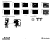
Accessories
Straight Bracket #60--2656 Apertures
(Transmitted Beam Only)
Right Angle Bracket #60--2657
15
(0.059)
Ref
42.4
(1.67)
R15
(0.59)
15.7
(0.62)
30_
3Places
018.5
(0.728)
29
(1.143)
12.7
(0.50)
53
(2.10)
35.8
(1.41)
1.5
(0.059)
Ref
42.4
(1.67)
12.7
(0.50)
29
(1.143)
R24
(0.95)
18.5 (0.728)
Note: 18mm nut must be installed
prior to installing aperture if threads
on optics snout are to be used.
4.6
(0.181) 4 Plc
4.6
(0.181)
4Plc
35.8
(1.41)
3Plc
Swivel/Tilt Bracket #60--2649
15.7
(0.62)
57.15
(2.25)
28.6
(1.125)
50.08
(2.0)
7.95
(0.31)
1mm Q ty. 20 #60- 2660
2mm Q ty. 20 #60- 2661
4mm Q ty. 20 #60- 2662
Aperture Set (4 each) #60- 2659
90_
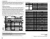
Cordsets and Accessories
Description Catalog Number
2m (6.5ft) micro QD Cordset 1485R--P2R5--C
2m (6.5ft) micro QD Patchcord 1485R--P2R5--F5
RS--232 PC Interface Module 1770--KFD
DeviceNet Manager Software 1787--MGR
PCMCIA DeviceNet Interface Card 1784--PCD
DeviceNet Hand-Held Configurator 2707--DNC
Reflector, 3I Diameter
92--39
Reflector, 1.5I Diameter
92--47
Other DeviceNet Products See Pub. DN--2.5
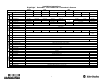
Data Byte 1
Bit 0 Bit 1 Bit 2 Bit 3 Bit 4 Bit 5 Bit 6 Bit 7
Output Diagnostic Margin 1 Margin 2 Motion Detect Counter Output Not Used Not Used
0 OFF OK OK OK Motion Less Than Preset
1 ON ALARM Margin Unstable Margin Unstable No Motion Preset Reached
Target
Note: Due to the detection method, targets traveling horizontal to
the sensor ’s optics are detected. Targets traveling vertically may
not be accurately detected. For reliable background suppression,
a minimum separation distance of 6mm (0.24in) is recommended
between the target and the backgrounds.
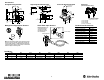
Background Suppression Sensors Glass Fiber Optic Sensors
Sensitivity Adjustment
Retaining
Clip
Groove in end tip
Note: RightSight fiber optic
models require Series C
glass fiber optic cables
with retaining grooves in
the control end tips.