
Manual

2
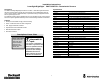
Table 1: User Interface
LED Color State
Status—
Teachable and Adjustable Versions
Status—
Transmitted Beam Receiver
Yellow
OFF Output de-energized
ON Output energized
Flashing NA Output SCP active
Orange
OFF Normal operation Margin <2.5x
ON Teach Mode Active Margin >2.5x
Flashing Teach Mode Active NA
Green
OFF Sensor not powered
Sensor not powered, output on,
or SCP active
ON Sensor powered
Flashing
Unstable margin condition (0.7x to 2.0x) or
output SCP active
NA
Note: For laser models, output and margin LEDs flash simultaneously when SCP active.
Mounting the Sensor
Securely mount the sensor on a firm, stable surface or support. A mounting which is
subject to excessive vibration or shifting may cause intermittent operation. Refer to
www .ab.com/ sensors for information on vertical and horizontal adjustment as well as
fixed mounting brackets. The sensor is supplied with a single 18 mm mounting nut for
either nose or base mounting options.
Wiring the Sensor
The RightSight photoelectric sensor is available in either a 2 m cable or 4--pin DC micro
quick-disconnect as identified on page 1. Rockwell Automation recommends the use of
the 889D Series of cordsets and patchcords for the QD models. All external wiring
should conform to the National Electrical Code and all applicable local codes.
Configuring the Sensor
LaserSight RightSight photoelectric sensors are available in teachable, adjustable, and
non--adjustable versions. Availability is determined by the sense mode.
S Standard Diffuse: Teachable and manual adjustable (potentiometer)
S Polarized Retroreflective: Teachable
S Transmitted Beam: No adjustment
Follow the setup procedure below for the version of RightSight being configured.
Teachable Versions
LaserSight RightSight photoelectric sensors with a teach function contain a pushbutton
rather than a manual adjustment knob for adjusting the sensors sensitivity level. This
function allows the sensor to “learn” both the light and dark conditions (background and
target) presented to it and automatically adjusts sensitivity to its optimal level for the
application. Follow the steps below to configure the sensor for your specific application.
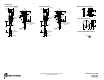
Ty pical Response Curves
Standard Diffuse—Beam Pattern
Polarized Retroreflective—
Beam Pattern
0100
(3.9)
Beam Diameter (mm)
Distance [mm (in.)]
-- 2
0
1
200
(7.8)
400
(15.7)
020
(65.6)
Beam Diameter (mm)
Distance [m (ft)]
-- 6
0
6
5
(16.4)
100
(328)
1
(3.3)
Operating Margin
Distance [m (ft)]
1000
100
10
1
10
(32.8)
Transmitted Beam—Margin
1
(0.04)
100
(3.94)
Operating Margin
Distance [mm (in.)]
100
10
1
10
(0.39)
1000
(39.4)
Standard Diffuse—Margin
1
(3.3)
100
(328)
Operating Margin
Distance [m (ft)]
100
10
1
10
(32.8)
0.01
(0.03)
Polarized Retroreflective—Margin
0.1
(0.33)
92--118 92--39
-- 1
2
300
(11.8)
-- 4
-- 2
2
4
10
(32.8)
15
(49.2)
1. Ensure that the sensor is securely mounted and wired. The green LED will be
illuminated indicating that power is applied to the sensor.
2. With the sensor pointed at the light condition (target for diffuse, reflector for polarized
retroreflective), press the pushbutton for five seconds and then release. The green
PWR/STAB LED will turn OFF and the orange SET/SCP LED will turn ON and start
flashing to indicate that the sensor has learned the light condition.
3. Present the dark condition to the sensor (no target for diffuse, target that blocks
reflector for polarized retroreflective) and press the teach button for five seconds and
then release. The orange SET/SCP LED will continue to flash while the teach
pushbutton is pressed. The green PWR/STAB LED will turn ON after the teach
button is released, indicating that the sensor is ready for normal operation.