
Manual

3
Wiring Diagrams
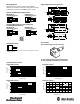
Quick disconnect connection is shown in the following
diagrams. Pin numbers correspond to an M12 male connector
on the sensor connected to an 889DS--F4AC--2 cordset
Diffuse and Background Suppression
Brown (1)
White (2)
Black (4)
Blue (3)
Load
Load
+
–
LO
DO
PNP Models with
Complementary Outputs
NPN Models with
Complementary Outputs
Brown (1)
White (2)
DO
Black (4)
Blue (3)
Load
+
–
LO
Load
Polarized Retroreflective, Clear Object and
Transmitted Beam Receiver
Brown (1)
White (2)
Black (4)
Blue (3)
Load
Load
+
–
LO
DO
PNP Models with
Complementary Outputs
NPN Models with
Complementary Outputs
Brown (1)
White (2)
DO
Black (4)
Blue (3)
Load
Load
+
–
LO
4
3
1
2
M12 Male
Transmitted Beam Emitter
Brown (1)
White (2)
Blue (3)
+
–
For normal operation, white wire (pin 2) needs no connection. To disable light source, connect
white wire (pin 2) to --V.
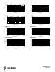
Approximate Dimensions [mm (in.)]
98.3
(3.87)
98.3
(3.87)
17.5
(0.69) Dia.
15.8
(0.63)
11.5
(0.45)
6
(0.24)
65
(2.56)
82.5
(3.25)
65
(2.56)
82.5
(3.25)
M12 x 1
M18 x 1
15.8
(0.63)
11.5
(0.45)
6
(0.24)
M12 x 1
71
(2.80)
2.2
(0.87)
LED
71
(2.80)
2.2
(0.87)
LED
Accessories
60-BCS-18B—Mounting bracket for smooth barrel
60- 2656—Straight mounting bracket for threaded models
60- 2657—Right angle mounting bracket for thread models
Typical Response Curves
10 100
(0.39) (3.9)
0 2030405060708090
Beam Diameter (mm)
Standard Diffuse (100 mm)
1
10
100
1000
0 1 10 100 1000
Distance [mm (in.)]
Operating Margin
90% white
paper
-- 1 5
-- 5
5
15
-- 1 0
0
10
Distance [mm (in.)]
Beam Pattern (100 mm)
90% white
paper
18%
(0.03) (0.39) (3.9) (39.37) (1.9)
18% grey
1
10
100
1000
Distance [mm (in.)]
Operating Margin
Standard Diffuse (400 mm) Beam Pattern (400 mm)
0 50 100 150 200 250 300 350 400
Beam Diameter (mm)
-- 3 0
-- 1 0
10
30
-- 2 0
0
20
Distance [mm (in.)]
90% white
paper
18% grey
0 1 10 100 1000
(0.03) (0.39) (3.9) (39.37) (1.9) (3.8) (5.9) (7.8) (9.8) (11.8) (13.7) (15.7)
90% white
paper
18% grey